A well cementing and fracturing device

A technology of cementing and outer casing, which is applied to wellbore/well components, production fluids, and earth-moving drilling, etc., can solve the problems of increased workload, difficulty in opening, and inability to guarantee the full diameter of the wellbore, so as to achieve cost savings, The effect of facilitating workover operations

Active Publication Date: 2018-03-30
陈晓新
View PDF8 Cites 0 Cited by
  • Summary
  • Abstract
  • Description
  • Claims
  • Application Information

AI Technical Summary

Problems solved by technology

The disadvantage of this cementing and fracturing sleeve is that the full diameter of the wellbore cannot be guaranteed after the fracturing is completed. To maintain the full diameter, additional drilling is required to remove the ball seat, which increases the workload.
[0005] The opening and closing of the second type of cementing and fracturing sliding sleeves are realized by special switch tools. Although the cementing and fracturing sliding sleeves ensure the full diameter of the wellbore, they must be isolated between layers. It is necessary to close the sliding sleeve in time to start the transformation of the next layer, and finally open the sliding sleeve selectively for production, which increases the workload
[0010] Chinese patent CN 204175272 U cannot guarantee the full diameter of the wellbore. To maintain the full diameter, additional drilling is required to remove the ball seat, which increases the workload
The Chinese patent CN 104895529 A can ensure the full passage of the wellbore. However, to achieve interlayer isolation, the sliding sleeve needs to be closed in time after the fracturing of the layer to start the transformation of the next layer, and when the sliding sleeve is opened, there will be Turn on difficult situations

Method used


Image

  • A well cementing and fracturing device
  • A well cementing and fracturing device
  • A well cementing and fracturing device

Examples


Embodiment Construction

[0053]The technical solutions of the present invention will be clearly and completely described below in conjunction with the accompanying drawings. Apparently, the described embodiments are some of the embodiments of the present invention, but not all of them. Based on the embodiments of the present invention, all other embodiments obtained by persons of ordinary skill in the art without making creative efforts belong to the protection scope of the present invention.

[0054] In the description of the present invention, it should be noted that the terms "center", "upper", "lower", "left", "right", "vertical", "horizontal", "inner", "outer" etc. The indicated orientation or positional relationship is based on the orientation or positional relationship shown in the drawings, and is only for the convenience of describing the present invention and simplifying the description, rather than indicating or implying that the referred device or element must have a specific orientation, o...


PUM


Abstract

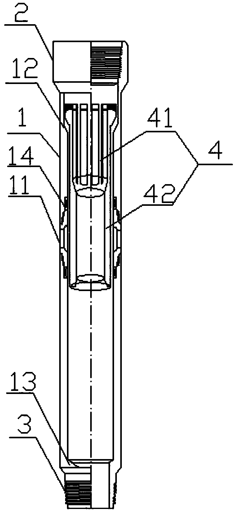
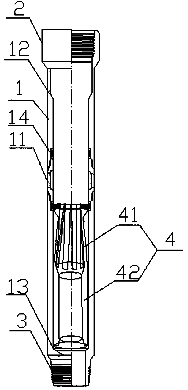
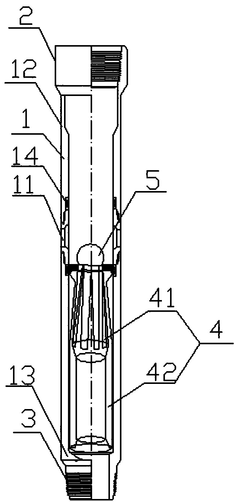
The invention provides a cementing and fracturing device. The device comprises an outer sleeve, and a soluble ball for blocking an upper channel and a lower channel of the outer sleeve, wherein an upper connector and a lower connector are correspondingly mounted at the upper end and the lower end of the outer sleeve; a circulating hole is formed in the sidewall of the upper part of the outer sleeve; an inner opened sleeve is arranged in the outer sleeve and is tightly matched with the outer sleeve; the inner opened sleeve comprises a lower inner opened sleeve, and a soluble ball seat which is arranged at the upper end of the lower inner opened sleeve; the soluble ball seat is closely wedged with the soluble ball; a first limiting part and a second limiting part for limiting the position of the inner opened sleeve are correspondingly arranged at the upper end and the lower end of the outer sleeve. The cementing and fracturing device are put down together with an oil pipe or a sleeve, so that the fracturing work can be continuously finished at a time, and as a result, the time can be saved; the perforation is avoided, so that the stratum can be prevented from polluting; after the fracturing is finished, the inside of the oil pipe or the sleeve remains all-pass state; additional bridge plug blocking layers are avoided, so that bridge plugs can be prevented from drilling and grinding, and as a result, the cost can be saved; the fracturing level number, the put-in quantity, the put-in depth and the fracturing flow of an oil and gas well are not limited.

Description

technical field [0001] The invention relates to the technical field of oil and gas well fracturing operations and cementing downhole tools, in particular to a cementing and fracturing device. Background technique [0002] Since the 1960s, fracturing technology has been widely used in stimulation operations of oil and gas fields in my country. The purpose of fracturing is mainly to improve the physical structure of the oil layer, artificially improve the permeability of the oil layer, so that the oil and gas wells can increase production. The essence of fracturing technology is to use high-pressure pumps to inject liquid with a certain viscosity into the formation at high speed. When the injection speed of the pump is greater than the absorption speed of the formation, the formation will be cracked or the original tiny gaps will be enlarged and opened to form larger cracks. With the continuous injection of liquid, the formed cracks continue to extend inward. In order to pr...

Claims


Application Information

Patent Timeline
Patent Type & Authority Patents(China)
IPC IPC(8): E21B33/13E21B43/26
CPCE21B33/13E21B43/26
Inventor 陈晓新
Owner 陈晓新
Why Eureka
Try Eureka