Eureka AIR delivers breakthrough ideas for toughest innovation challenges, trusted by R&D personnel around the world.
Density measuring device
What is Al technical title?
Al technical title is built by PatSnap Al team. It summarizes the technical point description of the patent document.
A technology for density measurement, measuring equipment, used in the field of fluids flowing in pipelines
Active Publication Date: 2016-08-24
ENDRESS HAUSER FLOWTEC AG
View PDF68 Cites 8 Cited by
Summary
Abstract
Description
Claims
Application Information
AI Technical Summary
This helps you quickly interpret patents by identifying the three key elements:
Problems solved by technology
Method used
Benefits of technology
Problems solved by technology
The disadvantage of such a correction based on measuring the viscosity of the medium guided in at least one measuring tube or on the attenuation of the desired oscillation depending thereon is in particular that the attenuation not only depends on the viscosity but also to a certain extent on the actual to-be-measured so that initially unknown medium density
Consequently, the density measurement determined by applying the viscosity or attenuation values generated by means of the electronics of the measuring device may in practice still have considerable, if not intolerable, measurement errors
Method used
Image
Click on the blue label to locate the original text in one second.
Reading with bidirectional positioning of images and text.
Examples
Embodiment Construction
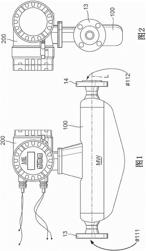
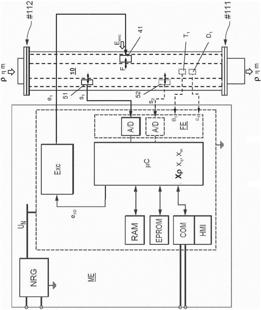
[0049] figure 1 with figure 2 A density measuring device is schematically shown in different side views for measuring the density of a medium, in particular a liquid or a gas, flowing in a process line (not shown) or for repeatedly determining the instantaneously expressed density The measured value (X ρ ). In a further embodiment of the invention, the density measuring device is furthermore configured to additionally also measure the viscosity of the medium or to determine a corresponding measured value (X η ). As an alternative or in addition thereto, the density measuring device can also be adapted to determine the mass flow, i.e. the total mass and / or the mass flow flowing during a predeterminable or earlier determined measuring interval, for the medium flowing in the pipeline, or to determine Correspondingly represents the measured value of the mass flow rate (X m ).
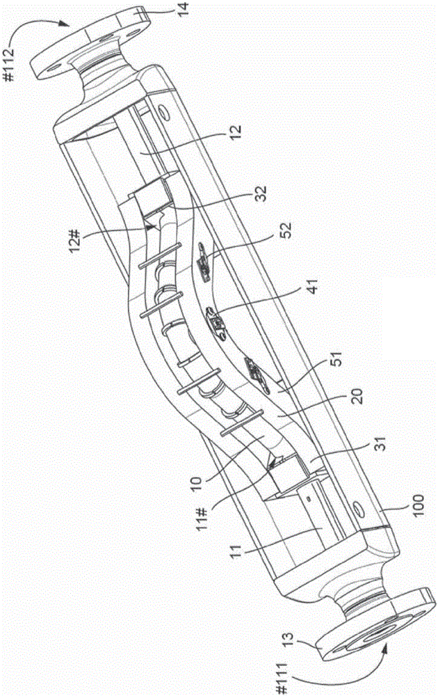
[0050] The density measuring device comprises a vibratory measuring transducer MW via inlet port ...
PUM
Abstract
The invention relates to a desity measuring device which is used to measure a density, rho, of a flowable medium and comprises measuring device electronics (ME) and a measuring transducer (MW) electrically connected to the measuring device electronics. The measuring transducer comprises a measuring tube (10), a vibration exciter (41) for exciting and maintaining vibrations, and a vibration sensor (51) for sensing vibrations of the at least one measuring tube. The measuring device electronics are designed to adjust, by means of a vibration measurement signal (s1) and an exciter signal (e1), a driving force that causes useful vibrations, namely vibrations having a specified useful frequency, fN, of the measuring tube, in such a way that a phase shaft angle, phi N, by which a velocity response, VN, of the measuring tube is phase shafted with respect to a useful force component, FN, of the driving force is less than -20 and greater than -80 degrees during a specified phase control interval, and / or the useful frequency has a frequency value that is more than 1.00001 times but less than 1.001 times a frequency value of an instantaneous resonance frequency of the measuring tube. Furthermore, the measuring device electronics are designed both to determine at least one frequency measured value, xf, representing the useful frequency for said phase control interval on the basis of the vibration measurement signal (s1) present during the phase control interval and to generate a density measured value, x rho, representing the density, rho, by using the frequency measured value, xf.
Description
technical field [0001] The invention relates to an electro-vibratory density measuring device for measuring the density p of flowable media, in particular fluids flowing in pipelines. Background technique [0002] As a rule, in industrial measurement technology, especially also with regard to the control and monitoring of automated manufacturing processes, in order to determine with high precision the density of a medium such as a liquid and / or gas flowing in a process line such as a pipeline, the application is by means of measuring device electronics Components (most often by means of at least one processor) and an oscillating measuring transducer that are electrically connected to the measuring device electronics and flow through during operation of the medium to be measured form a vibrating density measuring device. Such density measuring devices have been known for a long time, for example in the form of so-called four-conductor devices or so-called two-conductor device...
Claims
Application Information
Patent Timeline
Application Date:The date an application was filed.
Publication Date:The date a patent or application was officially published.
First Publication Date:The earliest publication date of a patent with the same application number.
Issue Date:Publication date of the patent grant document.
PCT Entry Date:The Entry date of PCT National Phase.
Estimated Expiry Date:The statutory expiry date of a patent right according to the Patent Law, and it is the longest term of protection that the patent right can achieve without the termination of the patent right due to other reasons(Term extension factor has been taken into account ).
Invalid Date:Actual expiry date is based on effective date or publication date of legal transaction data of invalid patent.