Flywheel and engine
A technology for engines and flywheels, which is applied in the direction of engine components, machines/engines, flywheels, etc., can solve the problems of increased crankshaft deflection, inability to ensure the maintenance space of the engine main body and flywheel body, and increase the deflection. Effect
- Summary
- Abstract
- Description
- Claims
- Application Information
AI Technical Summary
Problems solved by technology
Method used
Image

Examples
no. 1 Embodiment approach >
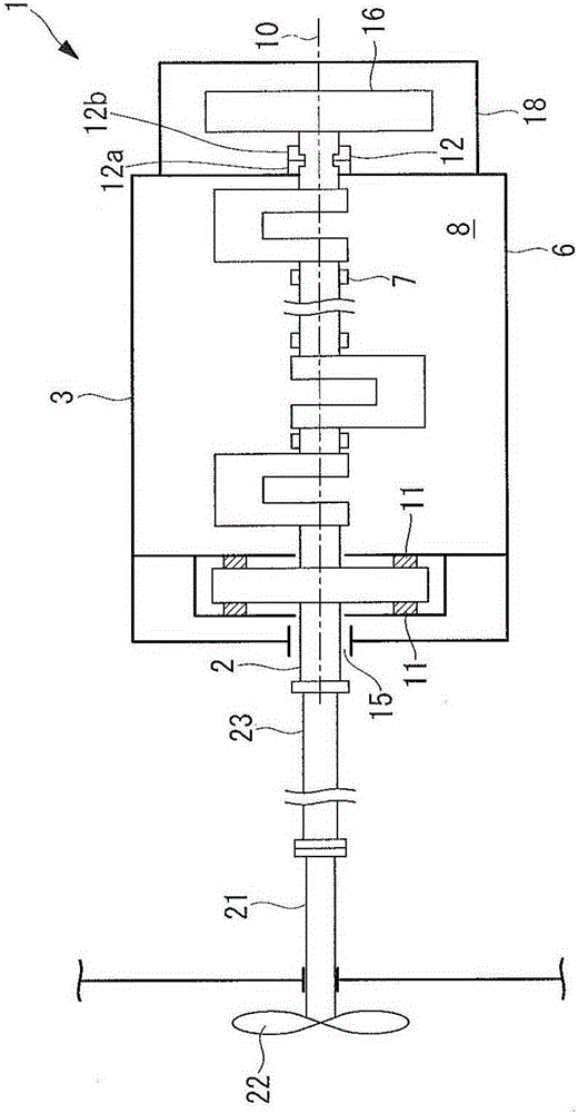
[0082] Hereinafter, an engine according to a first embodiment of the present invention will be described with reference to the drawings. The engine 1 is, for example, a marine diesel engine, which is disposed inside the hull of the ship, such as figure 1As shown, there is a crankshaft 2 and an engine body 3 . The crankshaft 2 has a pin portion connected to one end of a connecting rod, a journal portion supported by the pin portion and arranged on the axis 10 , and an arm portion connecting the pin portion and the journal portion.
[0083] The engine main body 3 has a frame 6 and a main bearing 7 . The machine base 6 is fixed to the hull, and a storage space 8 is formed inside. The pin portion and the arm portion of the crankshaft 2 are housed in the housing space 8 inside the engine body 3 , and both ends are arranged outside the housing space 8 . The main bearings 7 are respectively arranged in the storage spaces 8 , and the crankshaft 2 is rotatable about the axis 10 .
...
no. 2 Embodiment approach >
[0109] Next, a flywheel according to a second embodiment of the present invention will be described.
[0110] The flywheel 51 of the present embodiment is applicable to, for example, a flywheel provided on the front end side. Such as Figure 4 As shown, the flywheel 51 is formed in a disk shape and has a main body 52 , a split member 53 and a plurality of bolts 54 . The main body portion 52 is fixed to the crankshaft 2 and has a mounting surface 52a including a radial direction of a disk forming the flywheel 51 . The dividing member 53 is formed in a semicircular plate shape. The flywheel 51 is formed by attaching the divided member 53 to the attaching surface 52 a of the main body 52 . When attached to the main body 52 , the split member 53 forms a part of the side surface of the flywheel 51 (the side surface of the disk) and also forms a part of the engine body side surface (the bottom surface of the disk) of the flywheel 51 facing the engine body 3 .
[0111] The plural...
no. 3 Embodiment approach >
[0115] Next, a flywheel according to a third embodiment of the present invention will be described.
[0116] The flywheel 61 of the present embodiment is applicable to, for example, a flywheel provided on the front end side. Such as Figure 5 As shown, the flywheel 61 is formed in a disc shape and has a main body 62 , a split member 63 and a plurality of bolts 64 . In addition, the flywheel 61 only needs to be in the shape of a disc, and does not necessarily have to be a perfect circle. The main body 62 is fixed to the crankshaft 2, and has a mounting surface 62a formed on a chord corresponding to a center angle of the flywheel 61 which is less than 180 degrees. When viewed from the front, the split member 63 has a shape surrounded by an arc corresponding to a central angle of less than 180 degrees and a chord corresponding to the central angle of the arc. The flywheel 61 is formed by attaching the divided member 63 to the attaching surface 62 a of the main body 62 . When ...
PUM
 Abstract
Description
Claims
Application Information
 - R&D Engineer
- R&D Manager
- IP Professional
- Industry Leading Data Capabilities
- Powerful AI technology
- Patent DNA Extraction
Browse by: Latest US Patents, China's latest patents, Technical Efficacy Thesaurus, Application Domain, Technology Topic.
© 2024 PatSnap. All rights reserved.Legal|Privacy policy|Modern Slavery Act Transparency Statement|Sitemap