A special separator and spinner for spunbonded non-woven fabrics

A technology of spun-bonded non-woven fabrics and separators, which is applied in the direction of filament generation, non-woven fabrics, textiles, and papermaking, and can solve problems such as increasing the power and flow of suction fans, increasing the number of fibers, and limited improvement, and achieves Improve the uniformity of the tow, prevent the airflow from swirling, and improve the effect of controlling the direction of the tow

Active Publication Date: 2019-01-25
TIANDINGFENG NONWOVENS CO LTD
View PDF2 Cites 0 Cited by
  • Summary
  • Abstract
  • Description
  • Claims
  • Application Information

AI Technical Summary

Problems solved by technology

[0006] In the prior art, as described in the above two patents, setting a prismatic grid in the suction area of ​​the lapper and increasing the power and flow of the suction fan can improve the collection of ultrafine fibers, Reduce the flying flocs in the drafting process, reduce the fiber diameter, and increase the number of fibers; however, in the actual operation of the web-laying machine, the web forming curtain is in a stable moving state, and the prismatic grid under the suction area has limited improvement. The grid can increase the aperture or reduce the spacing; for increasing the power and flow of the suction fan, on the one hand, it increases the consumption of power energy; on the other hand, according to the principle of aerodynamics, the effective distance of the suction fan is limited. One-way movement, so when the fiber tow falls into the net, the movement state of the fiber filaments on both sides of the tow will be very different

Method used


Image

  • A special separator and spinner for spunbonded non-woven fabrics
  • A special separator and spinner for spunbonded non-woven fabrics

Examples


Embodiment

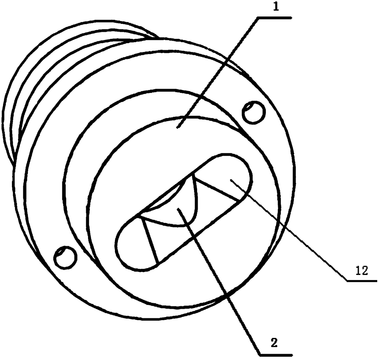
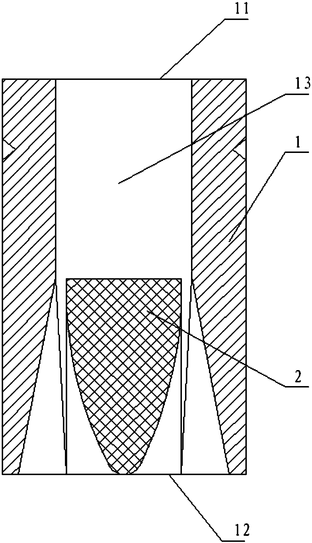
[0029] like Figure 1-2 A special spunbond non-woven fabric separator and spinner as shown, comprising a casing 1 and a shunt plug 2;

[0030] A gradual fluid channel 13 is formed inside the casing 1 from the inlet 11 end to the outlet 12 end;

[0031] The diverter plug 2 is disposed at the inner channel 13 at the end of the outlet 12 , and the cross-sectional area of ​​the diverter plug 2 gradually increases from the end of the outlet 12 to the end of the inlet 11 , and the diverter plug 2 is streamlined.

[0032] Further, the cross-section of the inner wall at the end of the inlet 11 is circular, and the cross-section of the inner wall at the end of the outlet 12 is a U-shaped or V-shaped ring.

[0033] Further, the cross section of the inner wall at the end of the outlet 12 is an irregular and smooth shape such as an ellipse, a rectangle with rounded corners, and the like.

[0034] Further, the diverter plug 2 is streamlined. The internal channel 13 and the shunt plug 2 ...


PUM


Abstract

A silk separator special for spun-bonded non-woven fabrics comprises a housing (1) and a shunting plug (2). A gradually varying fluid channel (13) is formed inside the housing (1) from an inlet (11) end and an outlet (12) end. The shunting plug (2) is arranged at the internal channel at the outlet (12) end, and a cross section of the shunting plug (2) is gradually increased from the outlet (12) end to the inlet (11) end. The silk separator has the following advantages that an outlet is designed to be in a shape of a U-shaped or V-shaped ring, the airflow direction can be effectively controlled, airflow swirling is prevented, the silk flock direction control in the web forming process is improved, and improvement of silk flock uniformity is promoted. The internal channel is in streamlined design, the cross section is gradually increased, silk flock diffusion is driven by airflow diffusion, and the silk separating purpose is achieved.

Description

technical field [0001] The invention relates to the technical field of non-woven fabric manufacturing equipment, in particular to a special spunbond non-woven fabric separator and spinner. Background technique [0002] In 1986, my country began to introduce spunbond production technology and equipment. There are only 3 spunbond production lines, with an annual output of 3,000 tons, accounting for only 3% of the country's total nonwoven production; in 2009, there were more than 600 domestic nonwoven production enterprises. , with over 1,000 production lines and a production capacity of 600,000 tons; there are 65 spunbond production lines of various brands at home and abroad, and the localization of equipment is 41.5%. The total production capacity is 202,800 tons. However, there is still a considerable gap between the technical level and foreign countries, and most of the equipment is at the international level in the early 1990s. Especially in spinning speed, web width, web...

Claims


Application Information

Patent Timeline
Patent Type & Authority Patents(China)
IPC IPC(8): D04H3/00D01D11/02
CPCD01D11/02D04H3/00
Inventor 张星云姜瑞明聂松林刘威理
Owner TIANDINGFENG NONWOVENS CO LTD
Why Eureka
Try Eureka