
Machine part loading and transporting box

A technology for mechanical parts and transport boxes, applied in the directions of internal parts, external parts, container handles, etc., can solve the problems of shortening the service life of loading and transporting boxes, increasing the work difficulty of staff, and easily damaged products for transportation, etc. Avoid manual dragging and shaking effects

Inactive Publication Date: 2016-08-24
WUXI MEIYANG POWER TECH CO LTD
View PDF6 Cites 5 Cited by
  • Summary
  • Abstract
  • Description
  • Claims
  • Application Information

AI Technical Summary

Problems solved by technology

[0002] At present, the transport box for mechanical parts is mainly composed of a top cover and a box body. When using the product, the product is placed in the box. Due to the special shape of the mechanical parts, there is usually a large remaining space in the transport box, so that the product is in the transportation process. Shake and collide with each other, easily damage the transported products. At the same time, after the existing mechanical parts transportation box is filled with mechanical parts, it must be moved by two people at the same time. This not only increases the staff's The work is difficult, and at the same time, it has a great wear and tear on the transport box, which shortens the service life of the loaded transport box

Method used

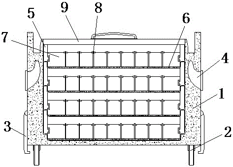
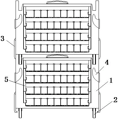
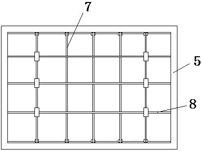

Image

  • Machine part loading and transporting box
  • Machine part loading and transporting box
  • Machine part loading and transporting box

Examples


Embodiment Construction

[0017] The following will clearly and completely describe the technical solutions in the embodiments of the present invention with reference to the accompanying drawings in the embodiments of the present invention. Obviously, the described embodiments are only some, not all, embodiments of the present invention. Based on the embodiments of the present invention, all other embodiments obtained by persons of ordinary skill in the art without making creative efforts belong to the protection scope of the present invention.

[0018] see Figure 1-3 , the present invention provides a technical solution:

[0019] A transport box for loading mechanical accessories, including a box body 1 and a box cover 9, moving pulleys 2 are installed on both sides of the bottom of the box body 1, and locks 3 are provided on the outer walls of both sides of the box body 1 to prevent the accessories from being transported Tilting or collapse occurs when stacked and stored, which has a certain protec...


PUM


Abstract

The invention discloses a machine part loading and transporting box which comprises a box body and a box cover, wherein movable pulleys are mounted on two sides of the bottom of the box body; part loading compartment layers are formed in the inner cavity of the box body; transverse baffles and longitudinal baffles are respectively arranged on the inner walls of the part loading compartment layers; the box cover is arranged at the top of the part loading compartment layers. The machine part loading and transporting box disclosed by the invention is simple in structure, and due to the transverse baffles and the longitudinal baffles arranged in the part loading compartment layers, machine parts can be respectively separated during loading, and the condition that the machine parts collide with one another during transportation is avoided. Meanwhile, a movable connection structure is formed between the part loading compartments and the transverse baffles and between the transverse baffles and the longitudinal baffles, so that an operator can freely adjust the distance between the transverse baffles and the longitudinal baffles when the machine parts are loaded. Therefore, the machine parts are stable during loading, and the condition that the machine parts shake during transportation is avoided.

Description

technical field [0001] The invention relates to the technical field of mechanical parts transportation, in particular to a mechanical parts loading transport box. Background technique [0002] At present, the transport box for mechanical parts is mainly composed of a top cover and a box body. When using the product, the product is placed in the box. Due to the special shape of the mechanical parts, there is usually a large remaining space in the transport box, so that the product is in the transportation process. Shake and collide with each other, easily damage the transported products. At the same time, after the existing mechanical parts transportation box is filled with mechanical parts, it must be moved by two people at the same time. This not only increases the staff's The work is difficult, and at the same time, it has a great wear and tear on the transport box, which shortens the service life of the loaded transport box. Contents of the invention [0003] The purpo...

Claims


Application Information

Patent Timeline
Patent Type & Authority Applications(China)
IPC IPC(8): B65D25/24B65D25/06B65D25/30B65D25/10B65D21/036B65D81/05
CPCB65D25/24B65D21/0209B65D25/06B65D25/10B65D25/30B65D81/05B65D2525/281B65D2581/051
Inventor 倪利刚
Owner WUXI MEIYANG POWER TECH CO LTD
Learn More