
Diaphragm and micro sounder provided with the diaphragm

A pattern and folding ring technology, applied in the field of micro sound generators, can solve problems such as difficulty in meeting the requirements of high sound quality of electronic equipment, inability to truly restore sound signals, creases or collapses of diaphragms, etc. Poor collapse, low distortion, high sound quality effects

Active Publication Date: 2019-04-30
GOERTEK INC
View PDF6 Cites 0 Cited by
  • Summary
  • Abstract
  • Description
  • Claims
  • Application Information

AI Technical Summary

Problems solved by technology

[0003] The surrounding ring part of the existing diaphragm usually has no pattern, or only a kind of concave pattern, that is, the convex direction of the pattern is opposite to that of the surrounding ring part, and the force direction of the diaphragm with this structure is the same when it vibrates , the diaphragm is easily deformed such as creases or collapses, resulting in polarization of the diaphragm, serious sound distortion, unable to truly restore the sound signal, poor sound quality, and difficult to meet people's requirements for high sound quality of electronic equipment

Method used


Image

  • Diaphragm and micro sounder provided with the diaphragm
  • Diaphragm and micro sounder provided with the diaphragm
  • Diaphragm and micro sounder provided with the diaphragm

Examples


Embodiment 1

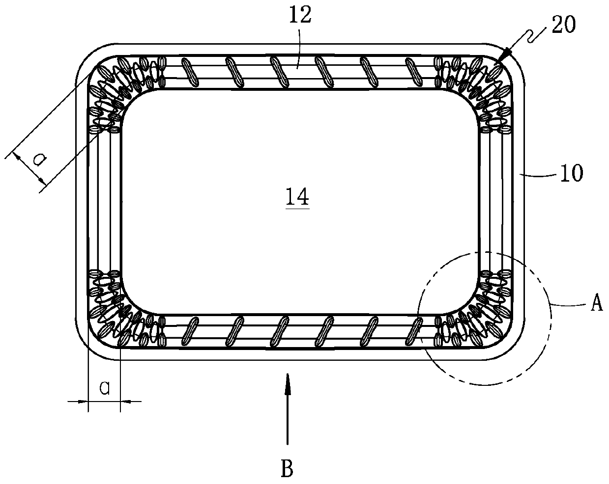
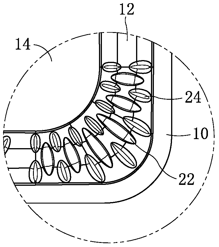
[0030] Such as figure 1 with image 3 As shown together, a vibrating membrane has a rectangular structure, including a spherical top 14 , a ring portion 12 and an edge portion 10 sequentially connected as one from the inside to the outside. The ring portion 12 is a rectangular ring-shaped structure, including two parallel four straight segments, and four curved segments connected between two adjacent straight segments, and the four curved segments constitute the ring portion 12. four corners. Patterns 20 are distributed on the ring portion 12 . In this embodiment, the patterns 20 are preferably concentrated and distributed at the four corners of the ring portion 12 , that is, four curved sections.

[0031] Such as figure 2 with Figure 4 Commonly shown, the pattern 20 at each corner includes two patterns with opposite convex directions, one is the convex pattern 22 whose convex direction is the same as that of the fold ring portion 20, and the other is the convex pattern ...

Embodiment 2

[0041] A miniature sound generator includes a vibrating system and a magnetic circuit system. The vibrating system includes a vibrating membrane and a voice coil combined together. The vibrating membrane is the vibrating membrane described in Embodiment 1.

[0042] Since the micro-speaker of the present invention adopts the diaphragm described in Embodiment 1, the distortion is greatly reduced, the sound reproduction effect is good, and the sound quality is high, which can meet people's requirements for high sound quality of electronic equipment.


PUM


Abstract

The invention discloses a vibrating diaphragm and a minitype acoustic generator with the same, and relates to the technical field of electroacoustic products. The vibrating diaphragm comprises a spherical top portion, a folded ring portion and an edge portion which are sequentially connected from inside to outside; patterns are distributed on the folded ring portion and comprise the convex patterns of which the convex direction is same as that of the folded ring portion and the concave patterns of which the concave direction is opposite to the convex portion of the folded ring portion. According to the vibrating diaphragm and the minitype acoustic generator with the same, the technical problem that in the prior art, a minitupe acoustic generator is serious in distortion is solved; the minitype acoustic generator with the vibrating diaphragm is little in distortion and high in sound quality and can meet the requirement of people for the high sound quality of electronic equipment.

Description

technical field [0001] The invention relates to the technical field of electroacoustic products, in particular to a vibrating membrane and a miniature sound generator provided with the vibrating membrane. Background technique [0002] Miniature sound generator is an important acoustic component in portable electronic equipment, which is used to convert sound wave electric signal into sound signal, and is an energy conversion device. The micro sounder usually includes a vibration system and a magnetic circuit system. The vibration system includes a diaphragm and a voice coil combined together. Important components play a vital role in the sound reproduction performance of the micro-sounder, which determines the conversion quality of the micro-sounder from electrical energy to sound energy. [0003] The surrounding ring part of the existing diaphragm usually has no pattern, or only a kind of concave pattern, that is, the convex direction of the pattern is opposite to that of ...

Claims


Application Information

Patent Timeline
IPC IPC(8): H04R7/12
CPCH04R7/122H04R2207/021
Inventor 马学敏
Owner GOERTEK INC
Learn More