
Electromagnetically Driven Micromirror with Bimetallic Coil

A technology for driving micromirrors and bimetals, used in optical components, optics, instruments, etc., can solve the problem of not being able to optimize the performance of micromirrors, and achieve the effect of reducing quality and improving response frequency

Inactive Publication Date: 2018-05-01
常州创微电子机械科技有限公司
View PDF5 Cites 0 Cited by
  • Summary
  • Abstract
  • Description
  • Claims
  • Application Information

AI Technical Summary

Problems solved by technology

The single-material coil cannot optimize the performance of the micromirror due to the limitations of the material itself.

Method used


Image

  • Electromagnetically Driven Micromirror with Bimetallic Coil
  • Electromagnetically Driven Micromirror with Bimetallic Coil
  • Electromagnetically Driven Micromirror with Bimetallic Coil

Examples


Embodiment Construction

[0020] The following will clearly and completely describe the technical solutions in the embodiments of the present invention. Obviously, the described embodiments are only some of the embodiments of the present invention, rather than all the embodiments. Based on the embodiments of the present invention, all other embodiments obtained by persons of ordinary skill in the art without making creative efforts belong to the protection scope of the present invention.

[0021] Embodiments of the invention include:

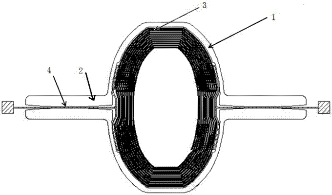
[0022] An electromagnetically driven micromirror with a bimetallic coil comprises a fixed frame, a mirror component is arranged inside the fixed frame, and a magnetic field system composed of a plurality of permanent magnets is arranged on the periphery.

[0023] like figure 1 As shown, the mirror assembly includes a twisted mirror plate 1, and the two sides of the twisted mirror plate 1 are respectively connected to the fixed frame through the torsion shaft 2. The said...


PUM


Abstract

The invention discloses an electromagnetic driving micro-mirror of a double-metal coil. A mirror surface assembly comprises a torsional mirror plate; the two sides of the torsional mirror plate are connected with a fixed framework through a torsional shaft respectively; a driving coil is wound around the torsional mirror plate; an input end lead wire and an output end lead wire are led out from the two sides of the driving coil respectively; the lead wires and the driving coil are two types of metal wires made of different materials; the thicknesses of the lead wires and the driving coil are adjustable. With the adoption of the manner, a double-metal material is used as the coil; a metal lead wire on the torsional shaft of the micro-mirror is made of a metal material with a smaller shear modulus, so that the rotary inertia of the torsional shaft can be reduced, and a rotary angle of the micro-mirror can be greater. The driving coil takes a metal material with smaller density as the coil, so that the weight can be reduced and the response frequency of the micro-mirror is improved; a ferromagnetic material is used and magnetic induction strength of the driving coil can be increased, so that the driving force is increased.

Description

technical field [0001] The invention relates to the field of micro-photoelectric motor systems, in particular to an electromagnetically driven micromirror of a bimetallic coil. Background technique [0002] In general, there are two main driving schemes for electromagnetically driven micromirrors: movable magnets and movable coils. Movable magnets use an external coil in combination with a magnet or deposited magnetic film. In the moving coil scheme, the coil is fabricated on the structure of the scanning mirror device, and an external magnet provides a static magnetic field. When the movable coil is fed with a changing current, the Lorentz force generated by the coil provides the torque for the vibration of the micromirror. [0003] Solutions using moving coils At present, coils generally use a single material (gold, nickel, copper, etc.). The single-material coil cannot optimize the performance of the micromirror due to the limitation of the material itself. Contents ...

Claims


Application Information

Patent Timeline
Patent Type & Authority Patents(China)
IPC IPC(8): G02B26/08
CPCG02B26/085
Inventor 沈文江余晖俊
Owner 常州创微电子机械科技有限公司
Learn More