
Shock wave pressure testing structure used in explosion near field

A pressure test and shock wave technology, applied in the field of explosion testing, can solve the problems of large vibration parasitic output, affecting the calculation of shock wave impulse value, and shock wave signal deformation, so as to reduce the impact and achieve the effect of accurate testing.

Inactive Publication Date: 2016-08-17
XIAN MODERN CHEM RES INST
View PDF8 Cites 12 Cited by
  • Summary
  • Abstract
  • Description
  • Claims
  • Application Information

AI Technical Summary

Problems solved by technology

During the measurement, the pressure sensor feels the impact of the seismic wave and the vibration of the installation base, and the output shock wave signal is often superimposed with the vibration signal, especially in the near field of the explosion. The vibration parasitic output is very large, which seriously affects the calculation of the shock wave impulse value.
[0003] In the past research work, in order to facilitate the installation and operation, the installation base of the pressure sensor is usually designed as a hollow shape inside, which makes the installation base vulnerable to the influence of seismic waves, and the output shock wave signal is seriously deformed
Later, the pressure sensor was installed on the component first, and then the component was installed on the installation base through the buffer gasket, which can reduce the impact of part of the vibration, but there will still be a large vibration parasitic output when the shock wave pressure test is carried out in the near field of the explosion.

Method used


Image

  • Shock wave pressure testing structure used in explosion near field
  • Shock wave pressure testing structure used in explosion near field
  • Shock wave pressure testing structure used in explosion near field

Examples


Embodiment 1

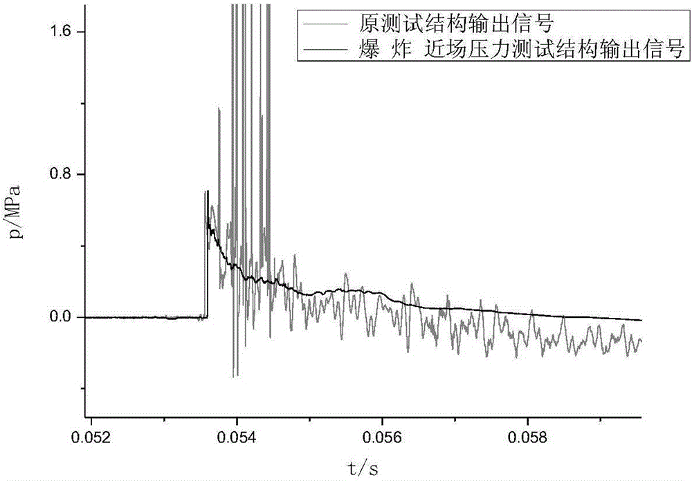
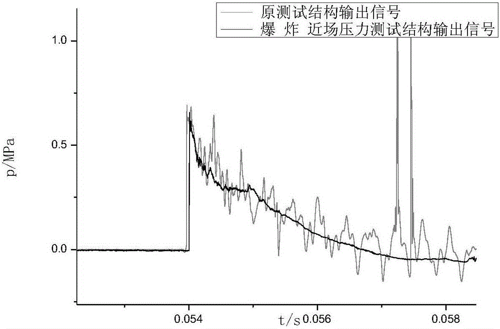
[0028] Use the PCB 113 pressure sensor as the test sensor, install it on the test structure, and place it at a position where the contrast distance from the blast center is 1. The shock wave pressure signal obtained is as follows: figure 2 Shown by the black solid line. image 3 In are the shock wave pressure signals obtained from the explosion of different ammunition. figure 2 and image 3 The middle gray solid line is the pressure signal obtained with the original test structure.

[0029] It can be seen that due to the impact of strong vibration on the original test structure, the shock wave signal is superimposed on the parasitic output of the pressure sensor caused by the vibration, and the ratio of the shock wave measurement deviation caused by the vibration to the peak value of the shock wave reaches a maximum of 30%. There are even superimposed signals that the rear circuit of the pressure sensor is suddenly disconnected or the signal line connector is vibrated and ...


PUM

PropertyMeasurementUnit
diameteraaaaaaaaaa
thicknessaaaaaaaaaa
diameteraaaaaaaaaa

Abstract

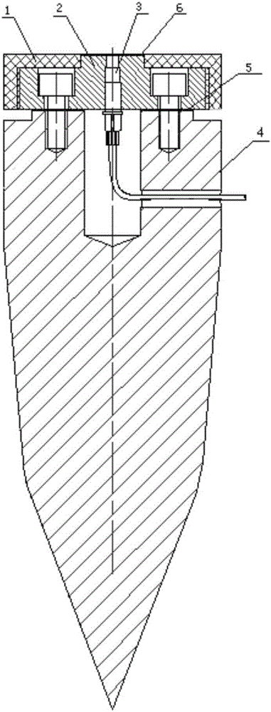
The invention relates to a shock wave pressure testing structure used in an explosion near field and belongs to the field of explosion tests. The shock wave pressure test structure is a pressure sensor mounting structure and can be put in the explosion near field for a shock wave ground reflection pressure test. The structure comprises an end cover, an upper cover, a pressure sensor, a base, an adhering layer and thermal-insulation grease, wherein the pressure sensor is mounted on the upper cover, and the upper cover is fastened to the base through inner hexagon screws after the upper surface of the base is coated with the adhering layer; the end cover is then screwed to the upper cover, and the overall structure is buried in soil; finally, the end surface of the pressure sensor and the end surface of the upper cover are smeared with the thermal-insulation grease, and end surfaces of the ground, the end cover, the upper cover and the pressure sensor are flush after mounting is completed. The shock wave pressure testing structure is used for the shock wave ground reflection pressure test in the explosion near field, and can control the ratio of the spurious output to a crest value of a shock wave caused by vibration within 6% and solve the problem of abnormal signals caused by vibration, thereby effectively reducing influences on test results from seismic waves and base vibration.

Description

technical field [0001] The invention belongs to the technical field of explosion testing, and in particular relates to a shock wave pressure testing structure. The structure is placed in the explosion near field to obtain a shock wave pressure curve. Background technique [0002] Shock wave pressure is an important basis for consideration in the assessment of blast field power. During the measurement, the pressure sensor feels the impact of the seismic wave and the vibration of the installation base. The output shock wave signal is often superimposed with the vibration signal, especially in the near field of the explosion. The vibration parasitic output is very large, which seriously affects the calculation of the shock wave impulse value. [0003] In the past research work, in order to facilitate the installation and operation, the installation base of the pressure sensor is usually designed as a hollow shape inside, which makes the installation base vulnerable to the influ...

Claims


Application Information

Patent Timeline
Patent Type & Authority Applications(China)
IPC IPC(8): G01L23/26
CPCG01L23/26
Inventor 孔霖苏健军胡东常李尚青陈君姬建荣魏巍
Owner XIAN MODERN CHEM RES INST
Learn More