Centrifugal brake mechanism of motor

A braking mechanism and centrifugal technology, applied in the field of motor braking system, can solve the problems of low reliability and complex structure of the motor braking mechanism, so as to improve the controllability, realize rapid start and stop, and long service life of the whole machine. Effect

Inactive Publication Date: 2016-08-17
SUZHOU KINGCLEAN PRECISION MACHINERY +1
View PDF10 Cites 4 Cited by
  • Summary
  • Abstract
  • Description
  • Claims
  • Application Information

AI Technical Summary

Problems solved by technology

The invention solves the technical problems of complex structure and low reliability of the motor braking mechanism

Method used


Image

  • Centrifugal brake mechanism of motor
  • Centrifugal brake mechanism of motor
  • Centrifugal brake mechanism of motor

Examples


Embodiment Construction

[0026] The present invention will be further described in detail below in conjunction with the accompanying drawings, so that those skilled in the art can implement it with reference to the description.

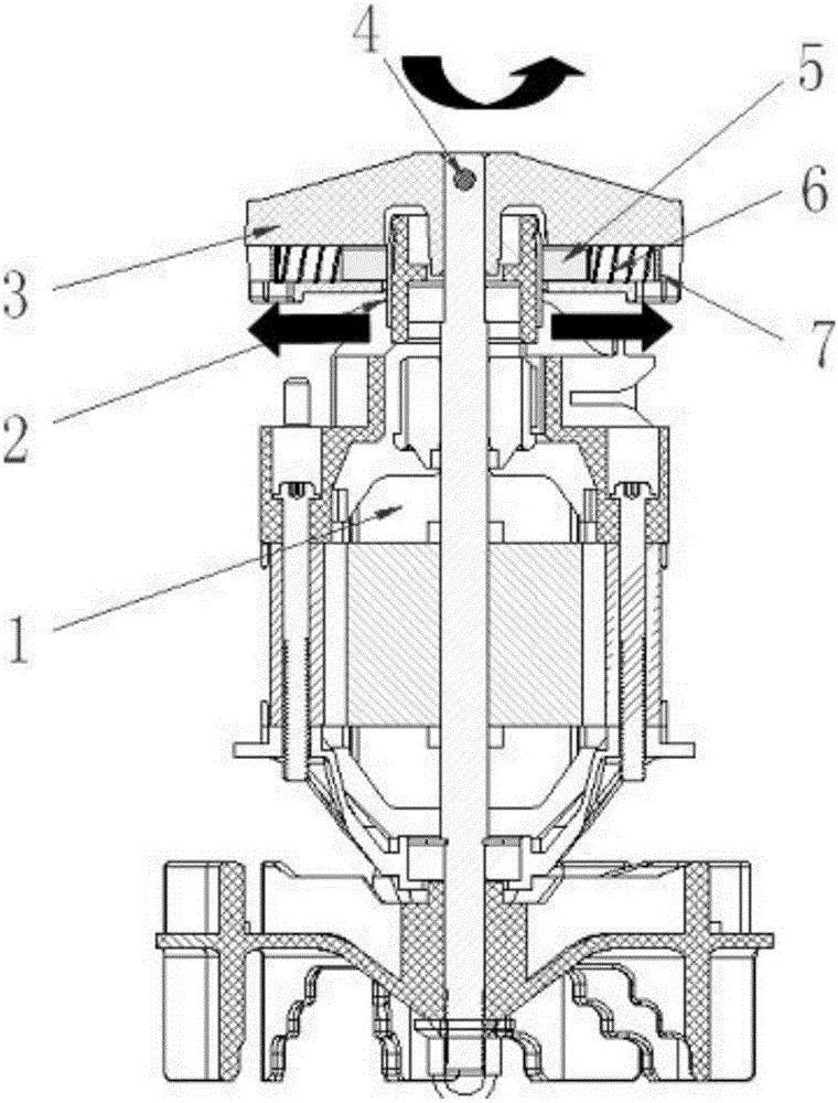
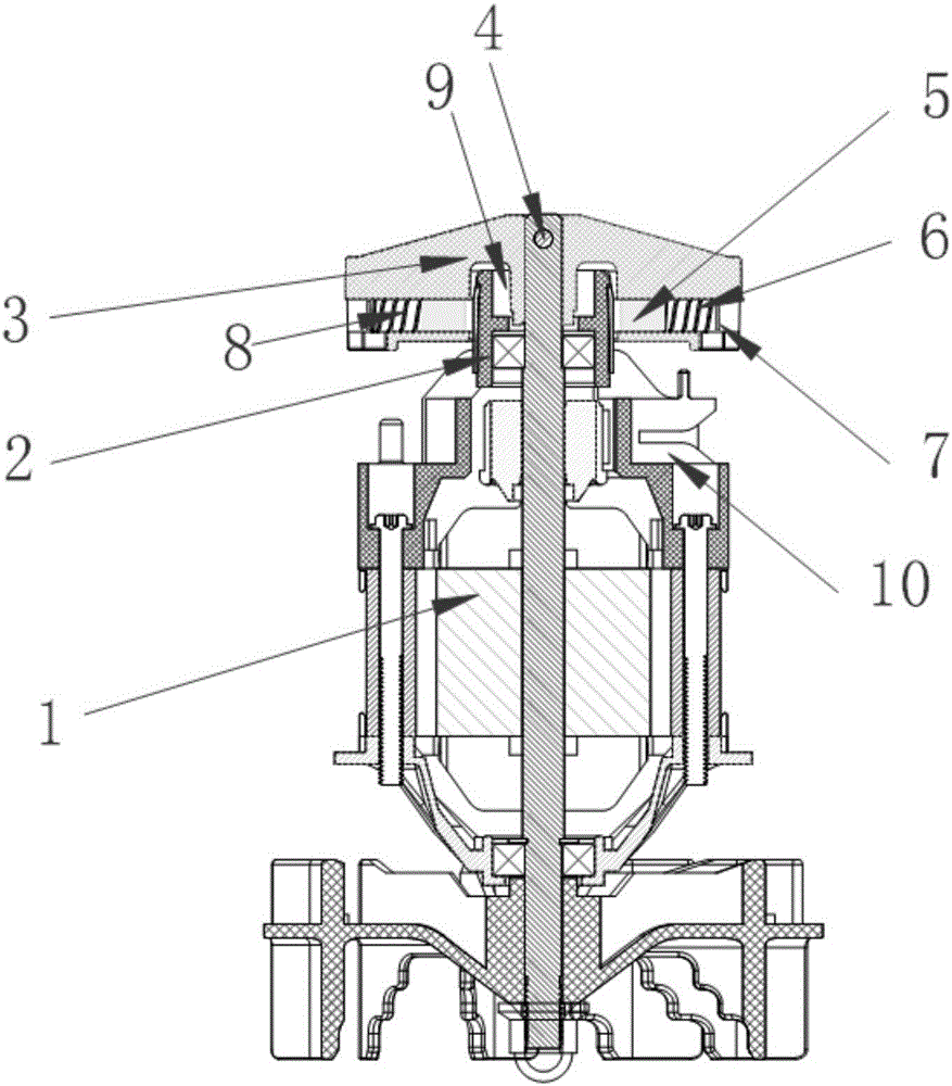
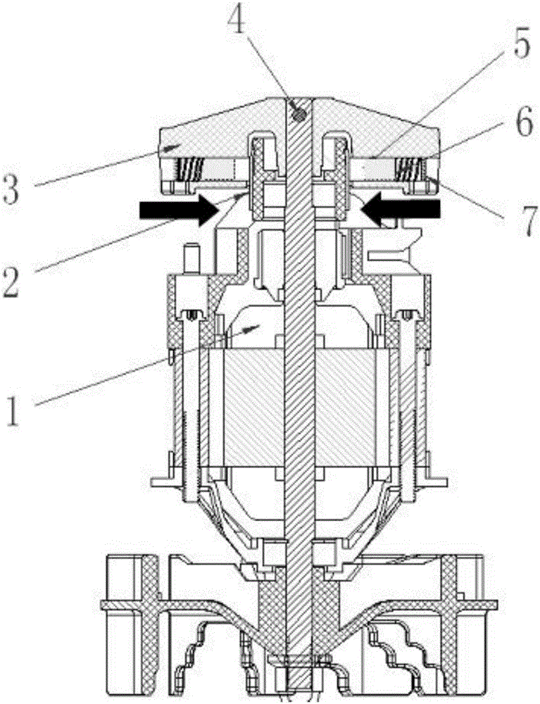
[0027] Such as Figure 1-4 As shown, the present invention provides a centrifugal brake mechanism for a motor, comprising: a motor 1, a brake ring 2, a brake bracket 3, a pin 4, a brake pad 5, an elastic device 6, and a brake pad 7 for braking, and the bracket 3 passes through the pin 4 It is fixed on the rotating shaft of the motor 1; the brake pad 5, the elastic device 6 and the brake stopper 7 are arranged on the brake bracket 3, and the brake bracket 3 rotates together with the motor shaft; the brake ring 2 is fixed on the upper bracket of the motor; when the brake pad 5 The received centrifugal force is less than the elastic force of the elastic device 6, and the brake pad 5 and the brake ring 2 contact and rub to realize braking. That is to say, the frictional force of...


PUM


Abstract

The invention discloses a centrifugal brake mechanism of a motor. The centrifugal brake mechanism comprises the motor, a brake ring, a brake bracket, brake pads and elastic devices, and the brake bracket is fixed to a rotating shaft of the motor; the motor drives the brake bracket to rotate around the brake ring, when the centrifugal force applied to the brake pads is smaller than elasticity of the elastic devices, the brake pads are in contact friction with the brake ring to achieve brake, and when the centrifugal force of the brake force is larger than elasticity of the elastic device, the brake pads are separated from the brake ring. The centrifugal brake mechanism solves the technical problems that the brake mechanism of the motor is complex in structure and not high in reliability.

Description

technical field [0001] The invention relates to a brake system of a motor, more specifically, the invention relates to a centrifugal brake mechanism of a motor. Background technique [0002] Electric tools, especially garden tools, require the whole machine to have a braking function to ensure that the operator will not be injured. Therefore, it is necessary to design a structure so that the motor can stop rotating quickly. [0003] With the improvement of living standards, people have higher and higher requirements for the greening level of living and living, and the large-scale ecological green spaces, residential green spaces, and road green spaces in cities continue to increase. Therefore, various garden tools are also continuously introduced. There are many defects in the mechanical brake mechanism of the tool, such as: the brake fails; the switch trigger is laborious to operate; the internal structure is not compact enough, resulting in a large and bulky appearance; T...

Claims


Application Information

Patent Timeline
Patent Type & Authority Applications(China)
IPC IPC(8): F16D59/02H02K7/102
CPCF16D59/02H02K7/102
Inventor 倪祖根
Owner SUZHOU KINGCLEAN PRECISION MACHINERY
Why Eureka
Try Eureka