
Movable steel arch bracing trolley

A steel arch, mobile technology, applied in the direction of wheels, vehicle parts, shaft lining, etc., can solve the problems of increasing the installation process of steel arch support equipment, increasing labor intensity, high risk, etc., and achieves a simple drive control system High efficiency, improved reliability and stability, and good ground adaptability

Active Publication Date: 2016-08-17
CHONGQING UNIVERSITY OF SCIENCE AND TECHNOLOGY
View PDF5 Cites 17 Cited by
  • Summary
  • Abstract
  • Description
  • Claims
  • Application Information

AI Technical Summary

Problems solved by technology

[0002] The initial support forms of tunnel engineering include sprayed anchor net support and steel frame anchored sprayed support. It is processed in sections in the factory outside the tunnel hole. Before installation, it is transported to the excavation site of the tunnel face. It is manually assembled on the ground into two sections on the left and right, and then assembled vertically. Connect the steel bars, install the steel mesh, and finally, spray the initial support concrete. The existing steel arch installation platform is only for the operators to climb to the installation position on the inner wall of the tunnel, and then manually lift each steel arch section to the installation position. This installation method is labor-intensive and slow, and the working surface of the arch installation is the excavation section just after excavation, the surrounding rock is unstable, and it is easy to cause problems such as falling rocks and injuring people, which is very dangerous. In addition, the existing steel arch support trolley is equipped with traveling wheels and moves through the rails laid in the tunnel. Therefore, the installation process of the steel arch support equipment is greatly increased, and the labor intensity is increased.

Method used


Image

  • Movable steel arch bracing trolley
  • Movable steel arch bracing trolley
  • Movable steel arch bracing trolley

Examples


Embodiment Construction

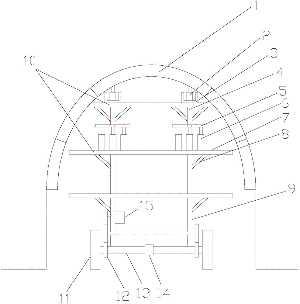
[0017] figure 1 It is a structural schematic diagram of the present invention, as shown in the figure, the movable steel arch 1 of the present embodiment supports the trolley, including the lower bracket 9, the upper bracket 4, and the deformation for supporting the lower bracket 9 and driving the lower bracket 9 to move. Wheel 11 and steel arch 1 jacking system; said steel arch 1 jacking system includes a jack group I6 arranged between the lower bracket 9 and the upper bracket 4 for jacking up the upper bracket 4 and a jack set on the top of the upper bracket 4 The jack group II2 for lifting the steel arch 1; the jack group I6 and the jack group II2 both include one or more jacks; in this embodiment, the upper bracket 4 and the lower bracket 9 include cross bars 10, columns and A chute 3 arranged longitudinally is fixed on the cross bar 10 of the inclined strut 8 and the upper bracket 4, and the jack group II 2 can be arranged in the chute 3 to facilitate the movement of the ...


PUM


Abstract

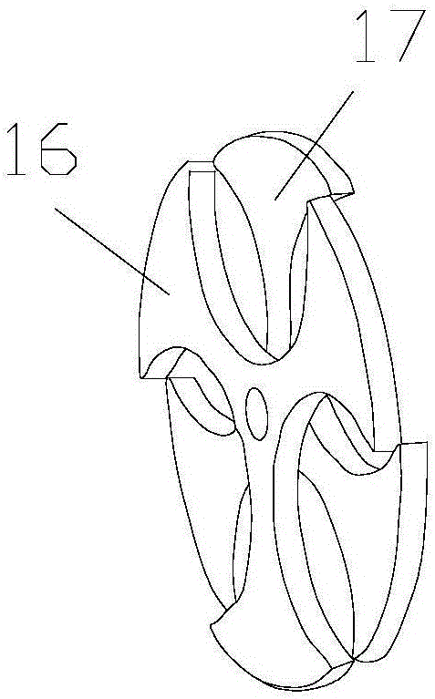
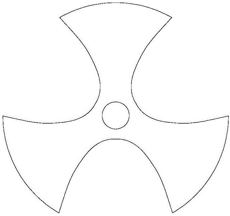
The invention discloses a movable steel arch bracing trolley comprising a lower stand, an upper support, a plurality of deformable wheels for supporting the lower stand and driving the lower stand to move, and a steel arch jacking system; the steel arch jacking system comprises a jack unit I which is installed between the lower stand and the upper support for jacking the upper support and a jack unit II which is installed on top of the upper support for jacking a steel arch; both the jack unit I and the jack unit II comprise one or more jacks; the deformable wheels of the trolley are able to deform by driving a certain mechanism, so as to greatly increase the trafficability characteristic of the trolley; while traveling on ordinary roads, the deformable wheels can be kept round, allowing a pile driver traveling steadily at a high speed.

Description

technical field [0001] The invention relates to the field of piling equipment, in particular to a movable steel arch support trolley. Background technique [0002] The initial support forms of tunnel engineering include sprayed anchor net support and steel frame anchored sprayed support. It is processed in sections in the factory outside the tunnel hole. Before installation, it is transported to the excavation site of the tunnel face. It is manually assembled on the ground into two sections on the left and right, and then assembled vertically. Connect the steel bars, install the steel mesh, and finally, spray the initial support concrete. The existing steel arch installation platform is only for the operators to climb to the installation position on the inner wall of the tunnel, and then manually lift each steel arch section to the installation position. This installation method is labor-intensive and slow, and the working surface of the arch installation is the excavation ...

Claims


Application Information

Patent Timeline
IPC IPC(8): E21D11/40E21D11/18B60B19/00
CPCB60B19/00B60B2900/325B60B2900/551E21D11/18E21D11/40
Inventor 王子健吴虹雨武黎明赵宝云王丽萍罗文文黄伟李晓蕾赵春花卓静罗玲潘颖高荣彭燕
Owner CHONGQING UNIVERSITY OF SCIENCE AND TECHNOLOGY
Learn More