Composite column and foundation joint structure with horizontal seismic performance and its construction method

A technology of horizontal earthquake resistance and node structure, applied in earthquake resistance, building components, building structure, etc., can solve the problems of consumption of concrete and steel bars, cracking of concrete protective layer, easy damage of concrete, etc., to achieve tensile and compressive strength. Improved, high strength, material saving effect

Inactive Publication Date: 2018-01-12
FUZHOU UNIV
View PDF6 Cites 0 Cited by
  • Summary
  • Abstract
  • Description
  • Claims
  • Application Information

AI Technical Summary

Problems solved by technology

Although the joints of this connection method are rigid, their ductility is poor, and the joints are easily damaged under the action of earthquakes, especially the concrete in the column-foundation joint area is easily damaged, resulting in cracking of the concrete protective layer, making its seismic performance insufficient
In addition, in order to ensure the strength and stiffness at the joints, the reinforcement ratio at the joints will be increased accordingly, and the net distance between the steel bars will be reduced at this time. Under the action of strong horizontal loads, once the concrete in the joint area cracks or damaged, the node is more likely to be damaged
In addition, for the structure of the joint between the single composite column and the foundation, the amount of concrete and steel bars used for the column and the foundation is relatively large, and the vertical steel bars in the column must go deep into the foundation and be bent and anchored after a certain depth, which brings great inconvenience to the construction. Certain difficulty and trouble

Method used


Image

  • Composite column and foundation joint structure with horizontal seismic performance and its construction method
  • Composite column and foundation joint structure with horizontal seismic performance and its construction method
  • Composite column and foundation joint structure with horizontal seismic performance and its construction method

Examples


Embodiment Construction

[0022] The present invention will be further described below in conjunction with the accompanying drawings and specific embodiments.

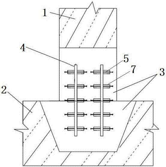
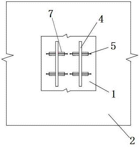
[0023] Such as Figure 1-4 As shown, a composite column and foundation node structure with horizontal seismic performance includes a composite column 1 and a foundation 2, and the poured concrete layer 3 at the connection node of the composite column and the foundation is connected as a whole, and the inside of the concrete layer At least two vertical steel plates 4 are buried horizontally, and several stud bolts 5 are arranged in a matrix on the surface of each vertical steel plate, and the stud bolts pass through the vertical steel plate surface vertically and are welded on the vertical steel plate, The head bolt and the vertical steel plate form a rigid body, and the two ends of the stud bolt are welded with nuts 6, which can improve the rigidity of the whole stud bolt. The casing 7 is made to be integrated with the peripheral part of the s...


PUM


Abstract

The invention relates to a combined column and foundation node structure with horizontal seismic performance and a construction method thereof. The combined column and foundation node structure comprises a combined column and a foundation, wherein the connecting nodes of the combined column and the foundation are integrally connected through a poured concrete layer, at least two vertical steel plates are transversely buried inside the concrete layer, a plurality of studs are arranged on the surface of each vertical steel plate in a matrix manner, the studs vertically penetrate the surface of the vertical steel plate and are welded to the vertical steel plate, nuts are welded to two ends of the studs, and a sleeve which is manufactured through ultrahigh-performance concrete pouring and used for being integrally connected with the periphery of each stud is arranged on the periphery of the stud. The combined column and foundation node structure has the advantages that the structure is convenient in construction and applicable to house building and bridges to increase the horizontal seismic performance of houses and the bridges, and the strength and ductility of the combined column and the foundation nodes are increased.

Description

technical field [0001] The invention provides a composite column and foundation node structure with horizontal seismic performance and a construction method thereof. Background technique [0002] At present, the conventional (composite) column-foundation joint construction is mainly to bind the vertical reinforcement and transverse reinforcement of the two and pour them together. Although the joints of this connection method are rigid, their ductility is poor, and the joints are easily damaged under the action of earthquakes, especially the concrete in the column-foundation joint area is easily damaged, resulting in cracking of the concrete protective layer, making its seismic performance insufficient . In addition, in order to ensure the strength and stiffness at the joints, the reinforcement ratio at the joints will be increased accordingly, and the net distance between the steel bars will be reduced at this time. Under the action of strong horizontal loads, once the conc...

Claims


Application Information

Patent Timeline
Patent Type & Authority Patents(China)
IPC IPC(8): E04B1/41E04B1/98E04H9/02
CPCE04B1/41E04H9/021
Inventor 庄一舟程俊峰黄福云李增锋
Owner FUZHOU UNIV
Why Eureka
Try Eureka