
Covered stent, manufacturing method thereof and sheath tube

A covered stent and film-covered technology, which is applied in the direction of stents, blood vessels, and devices with human tubular structures, to achieve the effect of improving the use effect and reducing the probability of new breaks

Inactive Publication Date: 2016-08-17
APT MEDICAL HUNAN INC
View PDF8 Cites 21 Cited by
  • Summary
  • Abstract
  • Description
  • Claims
  • Application Information

AI Technical Summary

Problems solved by technology

In the prior art, the sheath tube is also generally a linear tubular part, and when it is inserted into the blood vessel, it will also generate a straightening force like a stent graft, so during the delivery and release of the stent graft, it will also There is a safety risk of new blood vessel breaks

Method used


Image

  • Covered stent, manufacturing method thereof and sheath tube
  • Covered stent, manufacturing method thereof and sheath tube
  • Covered stent, manufacturing method thereof and sheath tube

Examples


Embodiment Construction

[0038] The present invention aims to provide a novel stent graft, which can further improve the use effect.

[0039] The following will clearly and completely describe the technical solutions in the embodiments of the present invention with reference to the accompanying drawings in the embodiments of the present invention. Obviously, the described embodiments are only some, not all, embodiments of the present invention. Based on the embodiments of the present invention, all other embodiments obtained by persons of ordinary skill in the art without making creative efforts belong to the protection scope of the present invention.

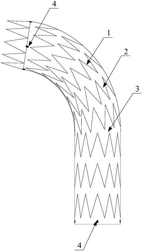
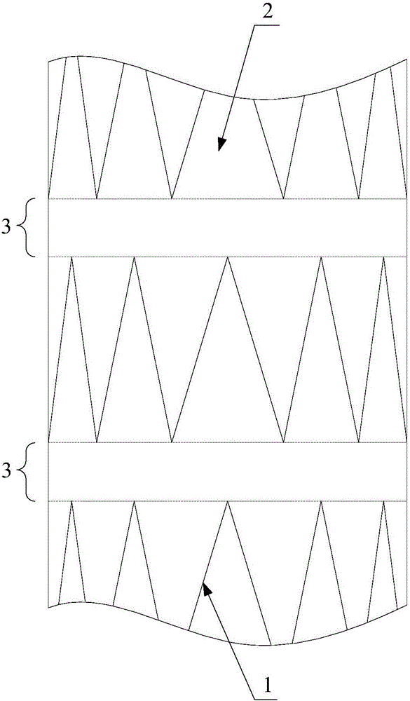
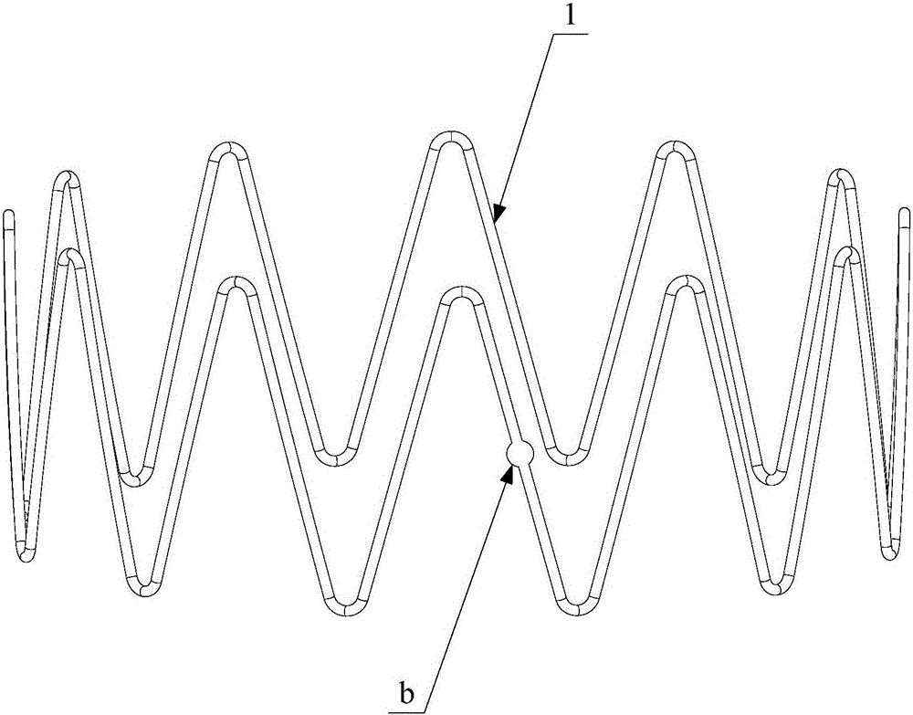
[0040] Such as Figure 1-Figure 7 As shown, the main improvement of the stent graft provided by the embodiment of the present invention is that there is a bending gap 3 for the stent graft 2 to be folded and wrinkled between different support frames 1 arranged adjacently in the axial direction. At the position where the bending gap 3 is located, only ...


PUM


Abstract

The present application discloses a stent graft, which includes a plurality of support frames and a film covered on the support frames to jointly form a tubular structure. In the axial direction of the tubular structure, any two adjacent support frames are A flex gap is left to allow the membrane to flex and fold. When the stent graft provided by the present invention is bent in a blood vessel, the bending part is a bending gap without a support frame, and only the stent graft is bent, and the whole stent graft has axial plasticity, that is, it can be shaped and maintain its own bending shape, so The straightening force generated is very small or even negligible; combined with the flexible sheath for delivery, the stent graft can conform to the bend of the vessel to the greatest extent when it is initially released, so as to significantly reduce the chance of new vascular rupture. The stent graft can also conform to the application of blood vessels with various bending angles, thereby significantly improving the use effect of the stent graft. The present invention also provides a method for manufacturing the above-mentioned stent-graft, and a sheath for delivering the above-mentioned stent-graft.

Description

technical field [0001] The present invention relates to the technical field of medical equipment, in particular to a stent-graft. The present invention also relates to a method for manufacturing the stent-graft. In addition, the present invention also relates to a sheath for delivering the stent-graft. Background technique [0002] When treating vascular diseases such as aneurysms, it is sometimes necessary to perform endovascular repair of aortic dissection to place a stent graft into the patient's blood vessel, so as to achieve the purpose of replacing and isolating the vascular lesion. [0003] The covered stent is composed of a ring-shaped bare metal stent and a membrane. Multiple identical bare metal stents are coaxially arranged, and the membrane is coated on the outside or inside of all the bare metal stents, thereby forming a tubular component, which is used to replace Diseased blood vessels divert blood. In the prior art, the stent-graft is generally an elastic str...

Claims


Application Information

Patent Timeline
IPC IPC(8): A61F2/07A61F2/966
CPCA61F2/07A61F2/0077A61F2/966A61F2240/001
Inventor 黄连军邱宇晨成正辉王端诚
Owner APT MEDICAL HUNAN INC
Learn More