Lifting support frame and display appliance

A support frame and utensil technology, which is applied in home utensils, applications, display hangers, etc., can solve the problems of narrow application range and easy damage of support plates, and achieve the effects of saving costs, reducing use costs, and simplifying the structure

Active Publication Date: 2019-08-06
CHANGZHOU HAWK DISPLAY SYST CO LTD
View PDF6 Cites 0 Cited by
  • Summary
  • Abstract
  • Description
  • Claims
  • Application Information

AI Technical Summary

Problems solved by technology

One end of the gas spring of the above patent is directly connected to the surface of the support plate, the support plate of the plastic part is easily damaged, and the scope of application is narrow

Method used


Image

  • Lifting support frame and display appliance
  • Lifting support frame and display appliance
  • Lifting support frame and display appliance

Examples


Embodiment 1

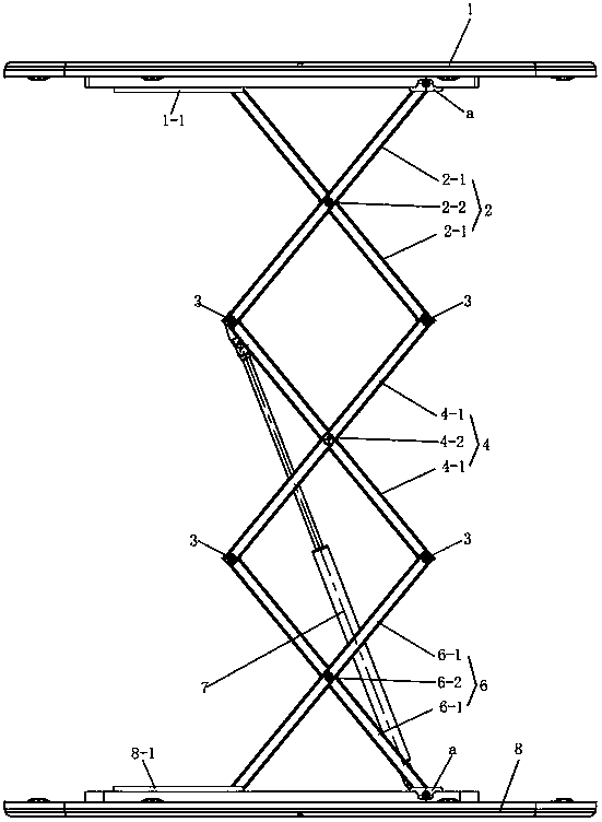
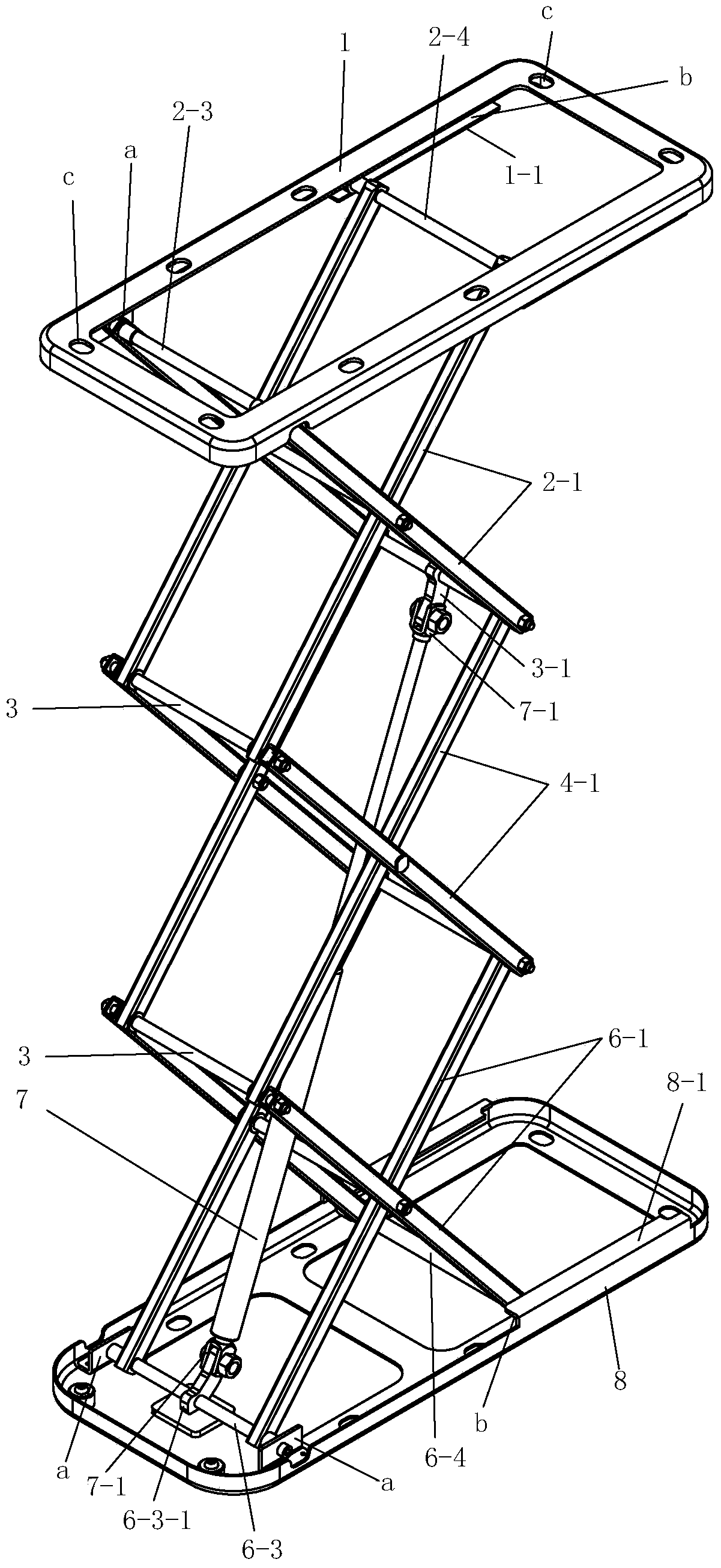
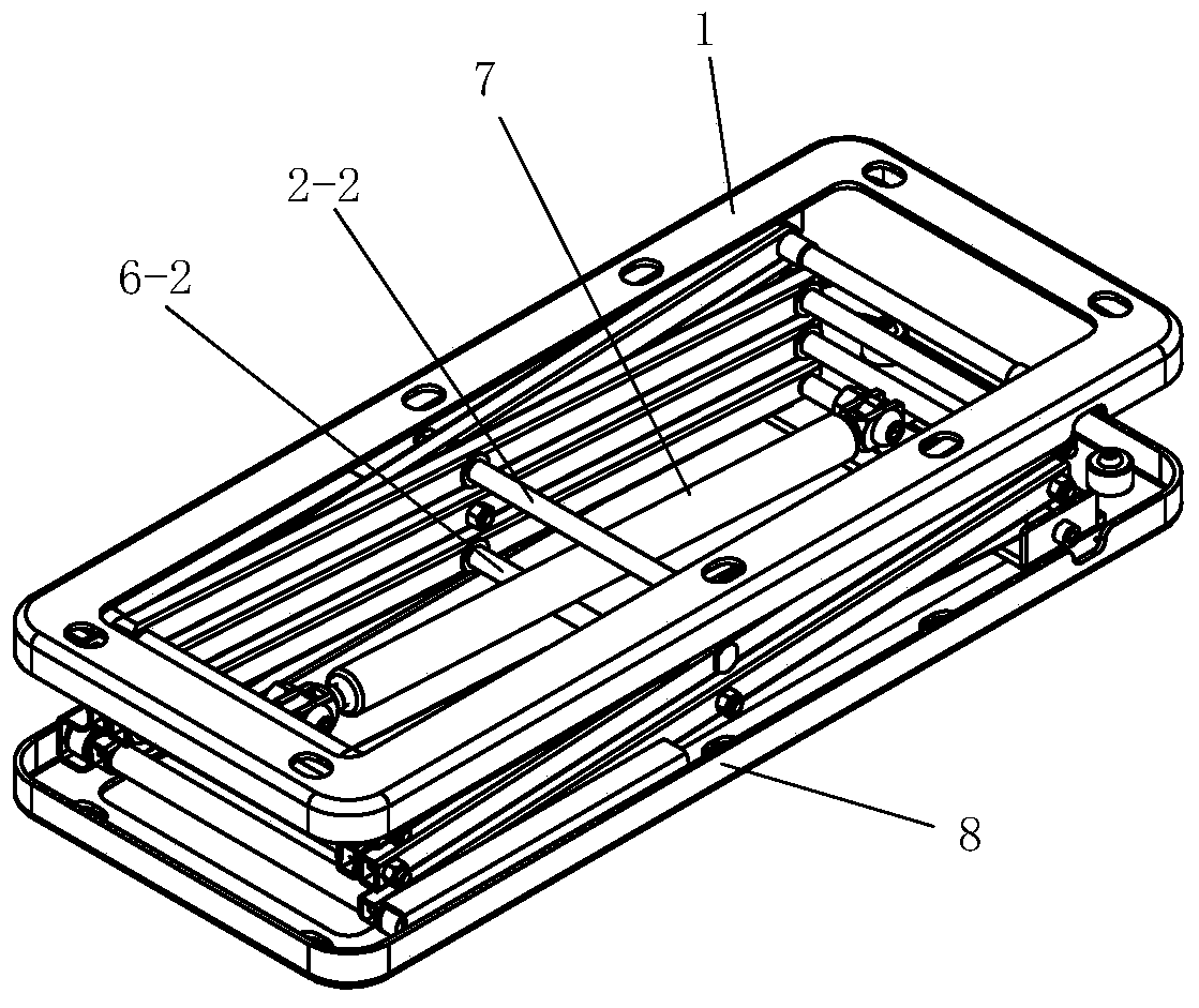
[0028] See Figure 1 to Figure 4 , This embodiment includes an upper connection frame 1, a three-dimensional grid-like lifting platform, a lower connection frame 8 and a power unit. The upper connection frame 1 and the lower connection frame 8 may be circular, elliptical, square, or rectangular, and the upper connection frame 1 or / and the lower connection frame 8 are provided with mounting holes c on the frame edge. The structure of the upper and lower connecting frames is the same. A pair of hinge seats a and a pair of guide grooves b are respectively provided at both ends of the connection frame. Formed by bending at right angles. The upper and lower connection frames are arranged symmetrically in a mirror image.

[0029] The three-dimensional grid-like lifting platform is located between the upper connecting frame 1 and the lower connecting frame 8. The three-dimensional grid-like lifting platform of this embodiment has three layers of grid units, which are respectively t...

Embodiment 2

[0036] See Figure 5 , the three-dimensional grid-like elevating platform of Embodiment 2 has four layers of grid units, namely an upper grid unit 2, a lower grid unit 6 and two middle grid units 4. Two pairs of connecting rods 4-1 of an intermediate grid unit 4 adjacent to the lower grid unit 6 are each hinged on the short pin shaft 4-2, that is, the lower intermediate grid unit 4 of the two intermediate grid units Each of the two pairs of connecting rods 4-1 is hinged on the short pin shaft 4-2, and the two pairs of middle connecting rods 4-1 of the upper middle grid unit 4 can be respectively hinged on the short pin shaft. The two pairs of middle connecting rods 4-1 of the upper middle grid unit 4 are respectively located at both ends of a middle-length pin shaft 4-3 and are hinged to the middle-long pin shaft 4-3. All the other are identical with embodiment 1. This structure is adopted for the three-dimensional grid-shaped lifting platform with more than four layers of g...

Embodiment 3

[0038] See Image 6 , the three-dimensional grid-like lifting platform of embodiment 3 has two layers of grid units, namely the upper grid unit 2 and the lower grid unit 6, one end of the gas spring 7 is hinged on the lower positioning rod 6-3, and the other end is hinged on the upper On the guide rod 2-4. All the other are identical with embodiment 1.

[0039] In the above-mentioned embodiments 1 to 3, the connection of the gas spring 7 can be that one end is hinged on the lower positioning rod 6-3, and the other end is hinged on the lower guide rod 6-4.


PUM


Abstract

The invention provides a hoisting supporting frame. The hoisting supporting frame comprises a three-dimensional grid-shaped hoisting platform, wherein the upper end and the lower end of the three-dimensional grid-shaped hoisting platform are connected with an upper connection frame and a lower connection frame respectively; an upper grid unit further comprises an upper positioning rod and an upper guide rod, which are connected between the upper ends of two pair of connection rods; the upper positioning rod is hinged between two hinging seats of the upper connection frame; the upper guide rod is in sliding connection with two guide grooves of the upper connection frame; a lower grid unit further comprises a lower positioning rod and a lower guide rod, which are connected between the lower ends of the two pair of connection rods; the lower positioning rod is hinged between two hinging seats of the lower connection frame; the lower guide rod is in sliding connection with two guide grooves of the lower connection frame; and a power device is an air spring; and the air spring is connected onto the lower grid unit or connected between the lower grid unit and a middle grid unit. With the adoption of the hoisting supporting frame, the structure is simplified; and the hoisting supporting frame is a whole body so that the hoisting supporting frame is very convenient to carry, store and use. Different parts are mounted on the hoisting supporting frame to form different appliances.

Description

technical field [0001] The invention relates to a support frame and a display appliance. Background technique [0002] Some of the display appliances are applied to the support frame, and the fixed support frame is inconvenient to carry and the height cannot be adjusted. The utility model of Chinese patent application No. 201420573336.2 discloses a pneumatic reception table, which includes an upper support plate and a lower support plate, a three-dimensional grid-shaped lifting frame is arranged between the upper and lower supporting plates, and the lifting frame is provided with at least two layers of mesh. grid unit, each layer of grid unit includes a horizontal bar and two hinged connecting rods connected to the left and right ends of the horizontal bar, between the connecting rod of the lower grid unit and the corresponding connecting rod of the upper grid unit The back of the upper and lower support plates are equipped with a guide groove perpendicular to the cross bar...

Claims


Application Information

Patent Timeline
Patent Type & Authority Patents(China)
IPC IPC(8): A47F5/10
CPCA47F5/10
Inventor 庄晓萍孙晓球
Owner CHANGZHOU HAWK DISPLAY SYST CO LTD
Why Eureka
Try Eureka