External-rotor variable excitation motor

A technology of external rotor and electric motor, which is applied in the direction of electric components, magnetic circuit rotating parts, magnetic circuit shape/style/structure, etc., and can solve the problems of motor full length lengthening, non-automatic variable excitation, pressure angle becoming large, etc. , to achieve the effect that the effect of the magnet will not decrease, the structure is simple, and the output is easy

Active Publication Date: 2016-08-10
SUZUKI MOTOR CO LTD
View PDF12 Cites 0 Cited by
  • Summary
  • Abstract
  • Description
  • Claims
  • Application Information

AI Technical Summary

Problems solved by technology

[0014] The variable field motor described in Patent Document 1 (Japanese Laid-Open No. 2014-50251) functions only in the forward rotation direction (forward in electric bicycles), but does not automatically perform variable field excitation in the reverse rotation direction or during regenerative braking.
In addition, since the cam and the cam follower are located near the central axis, when the displacement (lift amount) is large, the pressure angle becomes large, and an excessive force is applied to the cam follower (pin in Patent Document 1). , significant wear
[0015] According to the technique disclosed in Patent Document 1, the relative variable amount of each other (permanent magnet and electromagnet) is so small that it is not practical
In Patent Document 1, the variable amount is about 25% of the stacked thickness of the stator core. When the variable excitation amount is increased, the deflection amount (movable range) of the rotor increases, and the length of the spring also increases. Therefore, the overall length of such a motor becomes further longer

Method used


Image

  • External-rotor variable excitation motor
  • External-rotor variable excitation motor
  • External-rotor variable excitation motor

Examples


Embodiment Construction

[0095] Refer to the following side Figure 1 to Figure 14 shown attached Figure 1 Embodiments of the outer rotor type variable field motor of the present invention will be described in detail.

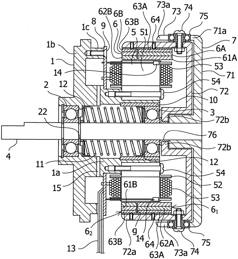
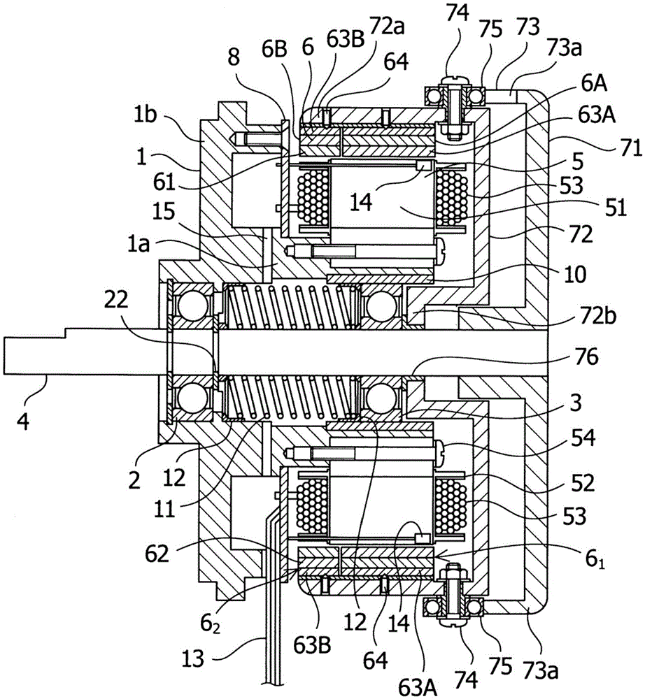
[0096] figure 1 It shows the structure of an open type outer rotor type variable excitation motor that automatically performs variable excitation in both forward and reverse rotation directions according to the magnitude of the load torque applied to a brushless motor. figure 2 is to use figure 1 A diagram of the state in which the inner rotor main body is moved by the action of the cam and the cam follower of the outer rotor type variable field motor.

[0097] exist figure 1 and figure 2 Among them, the outer rotor type variable field motor of the present embodiment includes: a motor main body 1; and a motor shaft 4 rotatably supported on the inner periphery of the cylindrical portion 1a of the motor main body 1 via a pair of rotary bearings 2 and 3. The surface side; the ...


PUM


Abstract

An outer rotor type variable excitation motor, which automatically performs variable excitation (variable speed) in both forward and reverse rotation directions according to the magnitude of the load torque, and it is also the same during regenerative braking. When the outer rotor slides in the direction of the motor shaft, the magnetic field characteristics of the outer rotor type variable excitation motor can be changed. The outer rotor (7) is a split structure consisting of the inner rotor main body (72) and the outer rotor body (72) sliding in the direction of the motor shaft. The rotor body (71) is composed of a main magnet (6A) and a sub-magnet (6B) arranged with a gap (g) in the axial direction and the magnet characteristics are opposite to each other, and a cam follower is arranged on the inner rotor body (72) (75), an axial cam surface (73a) is formed on the outer rotor main body (71), and the cam follower (75) can move along the cam surface (73a) according to the load applied to the motor shaft (4), The outer rotor (7) slides relative to the stator (5) in the direction of the motor shaft.

Description

technical field [0001] The present invention relates to the structure of an outer rotor type brushless motor, which uses a commutator type motor (DC motor with brushes), a rotary excitation type motor (permanent magnet rotor type motor), and uses load torque in both forward and reverse rotation directions. The size of the variable excitation (variable speed) is automatically performed, and it involves an outer rotor type variable excitation motor, which shifts the relative positions of the permanent magnets and the iron cores of the electromagnets in the direction of the motor shaft, and changes the mutual overlap. This is to perform variable excitation (weakening the excitation, etc.), in detail, use the cam to perform variable excitation, and use the relative movement amount (movable range) of the permanent magnet and the electromagnet to increase the effect of the variable excitation to 1 About twice as much as the column magnet type. Background technique [0002] Compar...

Claims


Application Information

Patent Timeline
IPC IPC(8): H02K1/27
CPCH02K5/1735H02K1/30H02K21/024H02K21/222H02K2213/09H02K1/2786
Inventor 酒井敏典
Owner SUZUKI MOTOR CO LTD
Why Eureka
Try Eureka