
Low-pressure injection molding magnetic proximity switch

A technology of magnetic proximity switch and low-pressure injection molding, which is applied in the direction of magnetic field/electric field switch, electric switch, contact electrical connection, etc. It can solve the problem of poor weather resistance and reliability of magnetic switch, and does not fully consider the connection structure of reed switch and lead wire Stability and other issues, to achieve high electrical connection strength, improve electrical stability, and stable performance

Inactive Publication Date: 2016-08-10
FOSHAN CHUANDONG MAGNETOELECTRICITY
View PDF4 Cites 8 Cited by
  • Summary
  • Abstract
  • Description
  • Claims
  • Application Information

AI Technical Summary

Problems solved by technology

[0004] The above scheme is mainly aimed at the purpose of fixing the reed switch in the plastic box and positioning it with glue, and does not fully consider the stability of the connection structure between the reed switch and the lead wire, and the weather resistance and reliability of the magnetic switch are not good.

Method used


Image

  • Low-pressure injection molding magnetic proximity switch
  • Low-pressure injection molding magnetic proximity switch
  • Low-pressure injection molding magnetic proximity switch

Examples


Embodiment Construction

[0021] The technical solutions of the present invention will be described below in conjunction with the accompanying drawings and embodiments.

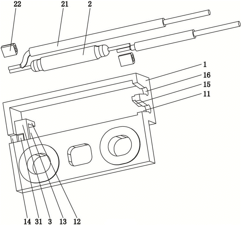
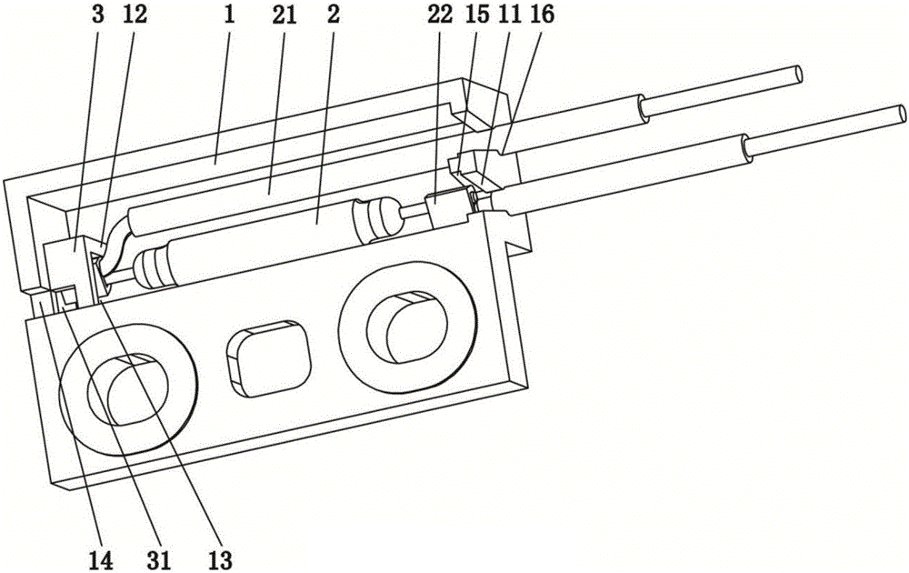
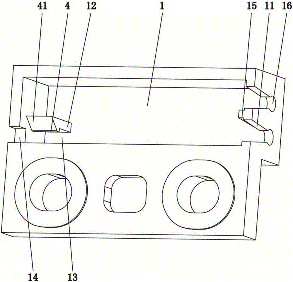
[0022] Such as Figure 1-2 As shown, a low-voltage injection-molded magnetic proximity switch according to the present invention includes a plastic box 1 with an opening at the upper end, a reed switch 2 and an incoming and outgoing lead wire 21, and two threading grooves are arranged on the right end wall of the plastic box 1 11. The inner side of the left end wall of the plastic box 1 is provided with a fixed line gusset 12, and the fixed line gusset 12 cooperates with one of the side walls of the plastic box 1 to form a fixed line opening 13; The two pins are electrically connected, and one of the pins of the reed switch 2 is fixed in the fixed line opening 13, and the incoming and outgoing lead wires 21 are respectively drawn laterally from the corresponding threading groove 11; the other pin of the reed switch 2 passes through th...


PUM


Abstract

The invention relates to the technical field of magnetic proximity switches, in particular to a low-pressure injection molding magnetic proximity switch, which comprises a plastic box, a reed switch and an inlet and outlet lead, wherein an opening is formed in the upper end of the plastic box; two threading slots are formed in the right end wall of the plastic box; a wire fixing pinch plate is arranged at the inner side of the left end wall of the plastic box; the wire fixing pinch plate is matched with the lateral wall of the plastic box to form a wire fixing opening; the inlet and outlet lead is electrically connected with two pins of the reed switch respectively; one pin of the reed switch is fixedly arranged in the wire fixing opening; and the inlet and outlet lead is transversely led out from the corresponding threading slot. The low-pressure injection molding magnetic proximity switch is reasonable in structure; one pin of the reed switch is integrally connected with the lead through a rivet; the electric connection strength is high; and the performance is stable. The rivet at one end of the reed switch is arranged in the wire fixing opening in a penetrating manner; the other end of the reed switch is limited through the positions of a wire clamping hole and a rib plate, so that the assembly position of the reed switch in an inner cavity of the plastic box is reasonable; a low-pressure injection molding process is achieved; and the impact strength and the electrical stability of the reed switch can be effectively improved.

Description

technical field [0001] The invention relates to the technical field of magnetic proximity switches, in particular to a low-voltage injection-molded magnetic proximity switch. Background technique [0002] Reed switch magnetic proximity switch is an on-off control switch that can realize non-contact magnetic triggering between two contacts of reed switch. Its reliability has been fully verified and it has been widely used as a safety control component. The reed switch is a fragile glass tube product, which is relatively easy to be damaged during the manufacturing and transportation process, resulting in switch failure, direct connection and other quality hazards. For this reason, the magnetic switch mostly adopts structural interference design, so that the reed switch can be effectively supported in the magnetic switch, thereby improving the accuracy of injection molding and improving the processing efficiency. [0003] For example, the magnetic proximity switch structure di...

Claims


Application Information

Patent Timeline
Patent Type & Authority Applications(China)
IPC IPC(8): H01H36/00H01H1/58H01H9/02
CPCH01H1/58H01H9/02H01H36/00
Inventor 龙克文徐晓兵
Owner FOSHAN CHUANDONG MAGNETOELECTRICITY
Learn More