
Dual-coil anti-magnetic-type current transformer

A technology of current transformers and double coils, applied in the field of electrical testing, can solve the problems of electrical signals being interfered by magnetic signals, inability to directly connect to measuring instruments, waste of electronic components, etc., and achieve simple manufacturing, simple structure, and accuracy strong effect

Inactive Publication Date: 2016-08-10
QINGDAO ITECHENE TECH CO LTD
View PDF5 Cites 8 Cited by
  • Summary
  • Abstract
  • Description
  • Claims
  • Application Information

AI Technical Summary

Problems solved by technology

[0003] The purpose of the present invention is to overcome the shortcomings of the prior art, and to design and propose a double-coil antimagnetic current transformer to solve the problem that the measured power system cannot be directly connected to the measuring instrument, and to solve the problem of the magnetic field in the automatic detection of electrical signals. The problem of signal interference, as well as the waste of electronic components and other materials, play a role in efficient anti-magnetic, and reduce economic costs

Method used


Image

  • Dual-coil anti-magnetic-type current transformer

Examples


Embodiment

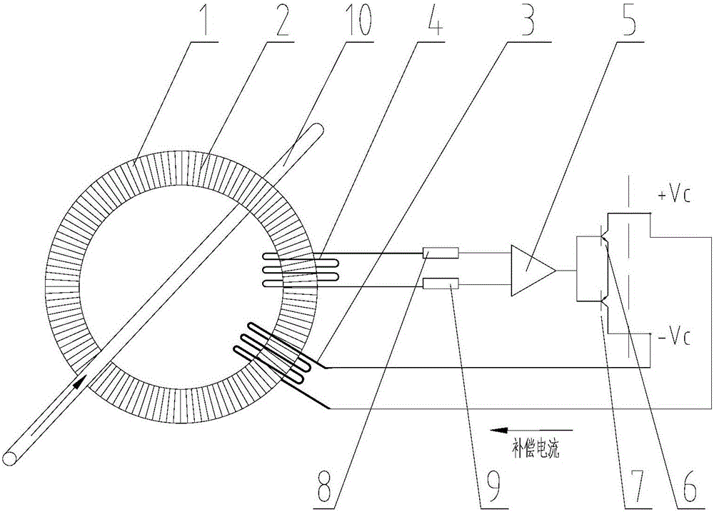
[0010] The main structure of the dual-coil antimagnetic current transformer involved in this embodiment includes: a magnetic ring 1, a primary coil 2, a compensation coil 3, an amplifier driving coil 4, an operational amplifier 5, a first triode 6, a second three The pole tube 7, the first resistor 8, the second resistor 9 and the measured terminal 10; the magnetic ring 1 is a magnetic material cylinder with a closed ring structure, and the primary side coil 2 adopts a dense structure formed by winding the magnetic ring 1 with insulated wires The two ends of the primary coil 2 are respectively connected to the measured end 10; the compensation coil 3 is a multi-turn coil formed by winding an insulated wire around the magnetic ring 1, and the winding direction of the compensation coil 3 is opposite to that of the primary coil 2 And the winding diameter of the compensation coil 3 is greater than the winding diameter of the primary coil 2; the amplifier driving coil 4 is a multi-t...


PUM


Abstract

The invention belongs to the technical field of electrical detection, and relates to a dual-coil anti-magnetic-type current transformer. A magnetic ring is in the form of a magnetic conductive material cylinder of a closed ring annular structure. The two ends of a primary-side coil are connected with a to-be-measured end respectively. A compensation coil and the primary-side coil are opposite in winding direction, and the winding diameter of the compensation coil is larger than the winding diameter of the primary-side coil. An amplifier drive coil and the primary-side coil are the same in winding direction. The coil diameter of the amplifier drive coil is larger than the coil diameter of the primary-side coil. The input ends of an operational amplifier are respectively connected with the two ends of the amplifier drive coil via a first resistor and a second resistor. The output ends of the operational amplifier are respectively connected with the two ends of the compensation coil via the docked collectors of a first triode and a second triode. The parameters of the first triode and the second triode are symmetrical. The dual-coil anti-magnetic-type current transformer is simple in structure, low in cost, efficient, anti-magnetic, good in linearity, high in precision, good in dynamic performance, high in accuracy, easy in production, and environment-friendly.

Description

Technical field: [0001] The invention belongs to the technical field of electrical detection, and relates to a double-coil antimagnetic current transformer, in particular to a high antimagnetic current transformer which uses a coil winding to induce the change of a measured signal and uses a compensation coil to eliminate magnetic interference. Background technique: [0002] With the expansion of urban population and construction scale, the increase of various electrical equipment, the electricity environment has become more and more complex; people often suffer from power supply and power system failures in their daily lives. The automatic detection and monitoring requirements of the system are getting higher and higher. In order to transmit electric energy, the power system often uses AC voltage and high current loops to send power to the user's power system, which cannot be directly measured by instruments. The measured value is convenient for the instrument to measure d...

Claims


Application Information

Patent Timeline
Patent Type & Authority Applications(China)
IPC IPC(8): G01R15/18
CPCG01R15/18
Inventor 李健达
Owner QINGDAO ITECHENE TECH CO LTD
Learn More