
Position limiting mechanism for transmission shifting and transmission

A technology of limit mechanism and transmission, applied in the direction of mechanical equipment, components with teeth, belt/chain/gear, etc., can solve the problems that the vehicle cannot start and drive normally, affects the normal operation of the engine, and reduces the service life, etc., and achieves benefits Smooth and normal operation, simple and practical structure, and convenient processing

Inactive Publication Date: 2016-08-10
CHONGQING LONCIN ENGINE
View PDF6 Cites 1 Cited by
  • Summary
  • Abstract
  • Description
  • Claims
  • Application Information

AI Technical Summary

Problems solved by technology

In the prior art, motorcycle transmissions have been optimally designed, and most gears are arranged in the gear setting of 1-0-2345, that is, from starting to normal driving, it is necessary to shift from neutral gear to first gear, and the first gear reaches a certain speed Then shift from the first gear to the second gear through the neutral gear, followed by the third gear, fourth gear, etc., and when the operation is wrong, it will be directly shifted from the neutral gear to the second gear in a static state, causing the vehicle to fail to start normally, and even to It will cause safety accidents, affect the normal operation of the engine, impact the transmission and reduce the service life

Method used


Image

  • Position limiting mechanism for transmission shifting and transmission
  • Position limiting mechanism for transmission shifting and transmission
  • Position limiting mechanism for transmission shifting and transmission

Examples


Embodiment Construction

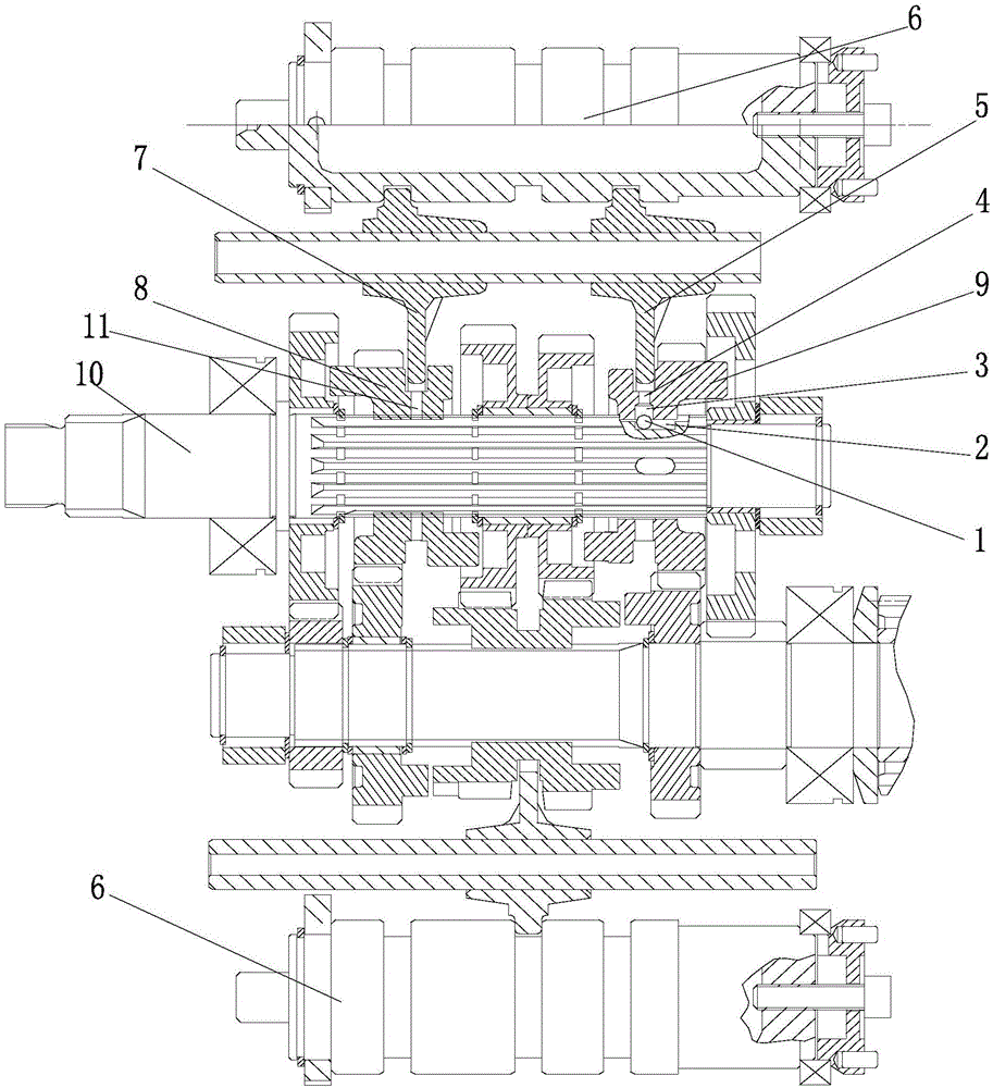
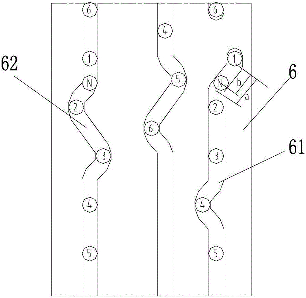
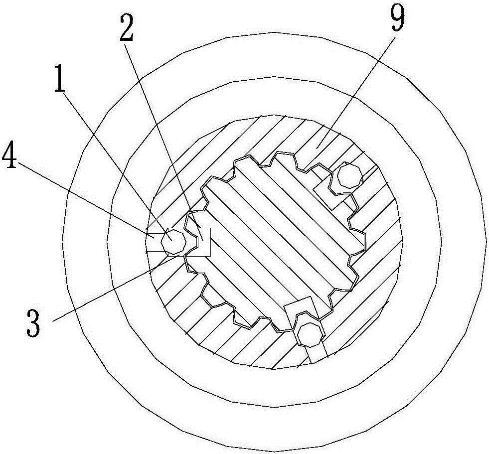
[0018] figure 1 Expand the structure diagram for the use state of the present invention, figure 2 Expand the structure diagram for the shift drive, image 3 It is a cross-sectional view of the limit mechanism (operating state of the transmission shaft), as shown in the figure, a limit mechanism for transmission shifting provided by the present invention includes a limit member 1, a limit groove 2 arranged on the drive shaft 10 and The accommodating groove 3 is arranged on the inner circle of the shift joint 9, the limiting groove 2 is opposite to the accommodating groove 3, and the limiting member 1 is placed in the limiting groove 2 and protrudes radially into the accommodating groove 3. The stop engaging member 9 is limited by the limiting member 1 to a position where it slides axially on the transmission shaft 10, and the radial size of the receiving groove 3 is sufficient to accommodate the limiting member 1 that is disengaged from the limiting groove 3 in the radial dir...


PUM


Abstract

The present invention provides a limit mechanism for gear shifting of a transmission and a transmission. The limit mechanism includes a limit member, a transmission shaft and a shift joint, the transmission shaft is provided with a limit groove, and the inner circle of the shift joint is provided with The accommodating groove, the limiting groove and the accommodating groove are opposite, and the limiting member is placed in the limiting groove and protrudes radially into the accommodating groove, and the shift joint is limited by the limiting member to axially slide on the transmission shaft position, the radial size of the receiving groove is sufficient to accommodate the limit piece that can break away from the limit groove in the radial direction. After running, the centrifugal force is used to release the limit position to ensure the smooth operation of the gear during normal operation, thereby facilitating the smooth and normal operation of the engine and transmission and prolonging their service life; this scheme is simple and practical in structure, low in cost, and does not need to change the original transmission structural arrangement.

Description

technical field [0001] The invention relates to a transmission equipment component, in particular to a limit mechanism for gear shifting of a transmission and a transmission. Background technique [0002] Shifting gears is an essential procedure and step for multi-speed transmissions, so that motor vehicles and other equipment can adapt to different operating environments; especially for motorcycles, when driving on different roads and using different driving speeds, different gears are required. Gear matching, so as to achieve a good running state. In the prior art, motorcycle transmissions have been optimally designed, and most gears are arranged in the gear setting of 1-0-2345, that is, from starting to normal driving, it is necessary to shift from neutral gear to first gear, and the first gear reaches a certain speed Then shift from the first gear to the second gear through the neutral gear, followed by the third gear, fourth gear, etc., and when the operation is wrong,...

Claims


Application Information

Patent Timeline
Patent Type & Authority Applications(China)
IPC IPC(8): F16H61/18F16H63/34
CPCF16H61/18F16H63/34
Inventor 周良兵闵渝维杜龙陈夏冬
Owner CHONGQING LONCIN ENGINE
Learn More