
Mud-water separation apparatus and mud-water separation method

A mud-water separation and equipment technology, which is applied in the field of mud-water separation equipment and mud-water separation, can solve the problems of ineffective control, increased energy consumption and cost, and large amount of flocculant, so as to increase the mud dehydration effect, save construction costs, and achieve large-scale treatment volume effect

Active Publication Date: 2016-08-10
上海尔速机械设备有限公司
View PDF6 Cites 8 Cited by
  • Summary
  • Abstract
  • Description
  • Claims
  • Application Information

AI Technical Summary

Problems solved by technology

For example, a horizontal screw discharge sedimentation centrifuge, referred to as a centrifuge, has the advantage of being able to work continuously for 24 hours, but it has high energy consumption, large amount of flocculant, high noise, low mud processing capacity, and the dry soil after treatment contains water. The ratio is 42-45%. If the moisture content is to be less than 40%, the residence time of the mud in the equipment will be prolonged, the energy consumption and cost will increase, and the output will decrease.
The advantage of the horizontal vacuum filter press is that the dehydrated mud is quite dry, and the energy consumption is low, but the output is low. The dry soil processing capacity per hour is 3 to 4 cubic meters, which basically cannot meet the requirements of construction projects.
The belt filter press has the advantages of low energy consumption and low manufacturing cost, but it is unstable during operation and cannot be effectively controlled

Method used


Image

  • Mud-water separation apparatus and mud-water separation method
  • Mud-water separation apparatus and mud-water separation method
  • Mud-water separation apparatus and mud-water separation method

Examples


Embodiment Construction

[0042] The idea, specific structure and technical effects of the present invention will be further described below in conjunction with the accompanying drawings, so as to fully understand the purpose, features and effects of the present invention.

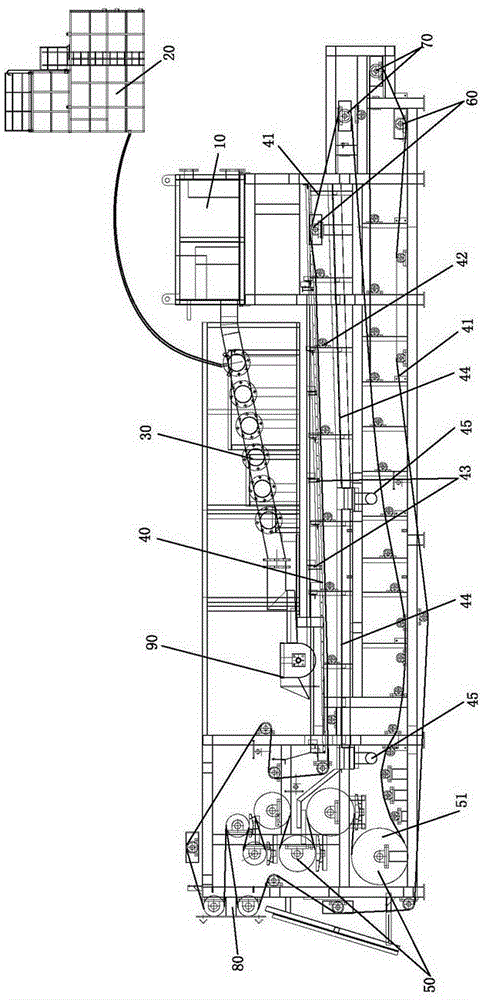
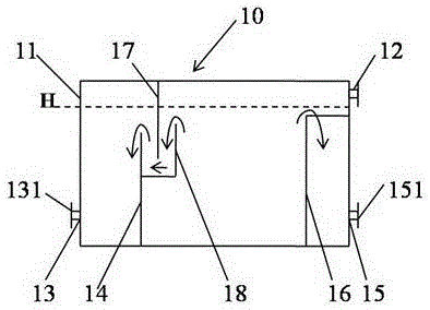
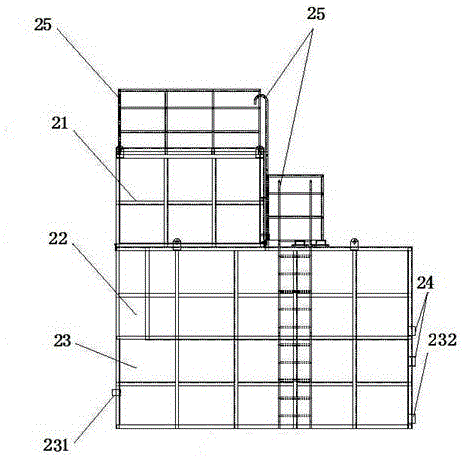
[0043] Such as figure 1 As shown, the pressure and flow stabilization device 10, the dosing box 20, the flocculation device 30, the homogeneous leveling device 90, and the concentration and dehydration device 40 in the mud-water separation device are successively arranged on the frame from high to low. The mud can complete the preliminary dehydration through the above-mentioned processes sequentially by its own gravity, and enter the pressure dehydration device 50 from the concentration dehydration device 40 . The mud outlet 13 of the pressure and flow stabilization device 10 is connected to a flocculation device 30 . The mixed medicine in the medicine adding box 20 enters the flocculation device 30 from the flocculant conveying p...


PUM


Abstract

The invention discloses a mud-water separation apparatus, comprising a pressure-stabilizing and flow-stabilizing device, a dosing tank, a flocculating device, a homogenizing and leveling device, a concentration and dehydration device and a pressurized dehydration device which are all arranged on a frame. A mud outlet of the pressure-stabilizing and flow-stabilizing device is connected with the flocculating device; a mixed reagent from the dosing tank enters the flocculating device via a flocculating agent conveyer pipe; mud obtained after flocculation flows out from the flocculating device and enters the concentration and dehydration device for preliminary dehydration via the homogenizing and leveling device and then enters the pressurized dehydration device for extrusion and dehydration; and dehydrated dry mud is transported out. The mud-water separation method comprises the following steps: (1) subjecting mud and a flocculating agent to a mixed reaction; (2) placing mud on filter cloth and allowing the mud to undergo stationary dehydration relative to the filter cloth; and (3) placing mud between two layers of the filter cloth and carrying out peristaltic dehydration through extrusion by a pressure roller. Compared with the prior art, the mud-water separation apparatus and mud-water separation method provided by the invention have the advantages of great efficacy, low energy consumption, high stability, great treating capacity, capacity of realizing continuous treatment, etc.

Description

technical field [0001] The invention belongs to the field of mud-water separation equipment, and is suitable for construction engineering, municipal engineering, shield engineering, river dredging, pipe network engineering of urban construction, etc., and specifically relates to a mud-water separation equipment and a mud-water separation method. Background technique [0002] In the field of mud-water separation equipment, a variety of separation equipment has been used in various places. For example, a horizontal screw discharge sedimentation centrifuge, referred to as a centrifuge, has the advantage of being able to work continuously for 24 hours, but it has high energy consumption, large amount of flocculant, high noise, low mud processing capacity, and the dry soil after treatment contains water. The slurry rate is 42-45%. If the moisture content is to be less than 40%, the residence time of the slurry in the equipment will be prolonged, the energy consumption and cost wi...

Claims


Application Information

Patent Timeline
IPC IPC(8): C02F11/14C02F11/12B01D33/04B01D33/056
CPCB01D33/042B01D33/056C02F11/121C02F11/123C02F11/14C02F2303/06
Inventor 丁明明
Owner 上海尔速机械设备有限公司
Learn More