
Box Die Cutting Machine

A die-cutting machine and packing box technology, applied in metal processing, etc., can solve the problems of incoherent film conveying, affecting production efficiency, inconvenient operation, etc., and achieve high processing efficiency, good die-cutting effect and simple structure

Active Publication Date: 2017-07-07
FUJIAN YINGHAO CULTURAL & CREATIVE CO LTD
View PDF5 Cites 0 Cited by
  • Summary
  • Abstract
  • Description
  • Claims
  • Application Information

AI Technical Summary

Problems solved by technology

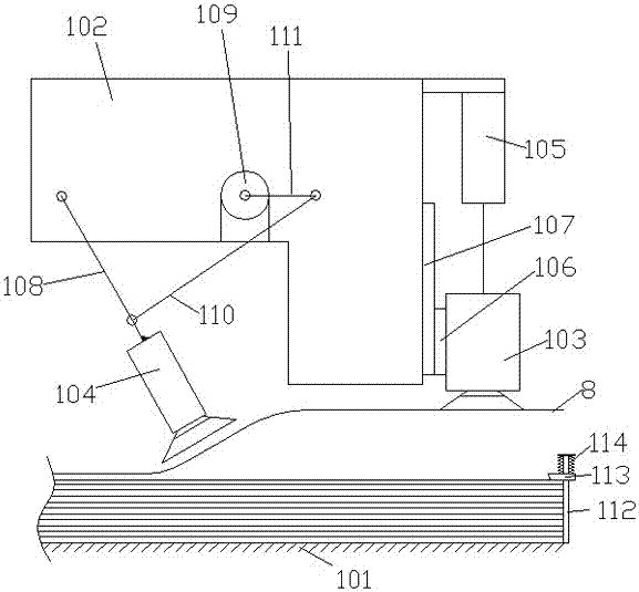
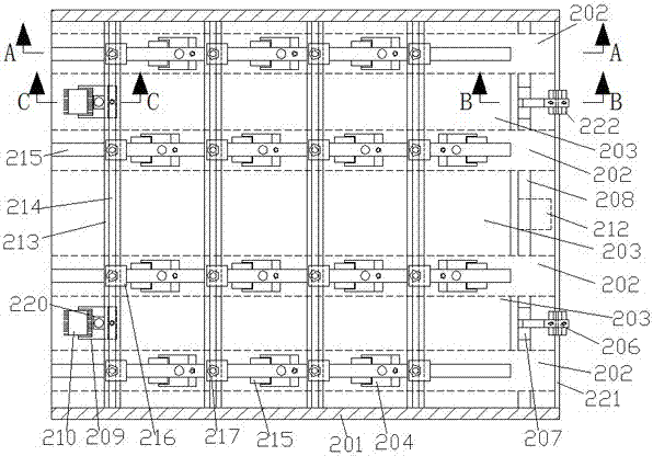
[0002] The existing packaging box die-cutting machine has the following problems. First, the film on the film stack often has the problem of wrinkling and the film on the film stack being scattered and irregular during the forward feeding and conveying process, and often There are multiple sheets of film adhered and overlapped together for feeding, which affects the processing efficiency and processing quality; second, the feeding and conveying mechanism of the packaging box die-cutting machine, when the film is fed forward and conveyed, the film often appears wrinkled 1. Too much pressing pressure will cause the film to be damaged or the film will be over-stretched and deformed. Too little pressing pressure will cause some parts of the film to stay and cause wrinkles and damage, and the film transportation will be incoherent and unstable, which will affect the processing efficiency and processing quality. ; Third, the die-cutting device of the die-cutting machine does not generally have a heating element. When performing die-cutting of plastic sheets, due to the large thickness of the plastic sheet, the die-cutting pressure needs to be adjusted frequently, which is inconvenient to operate and affects the quality of the plastic sheet. Die-cutting effect and work efficiency. At the same time, when the die-cutting mechanism of the flat die-cutting machine on the market is working, the paper sheet is easy to get stuck on the die-cutting knife, which makes the die-cutting work lose the efficiency and order it should have. ; Fourth, the unloading and receiving device of the flat die-cutting machine has a complex structure. The sheets after die cutting are stacked on the collection table one by one, and the stacking of the sheets is scattered and irregular. , seriously affecting production efficiency

Method used


Image

  • Box Die Cutting Machine
  • Box Die Cutting Machine
  • Box Die Cutting Machine

Examples


Embodiment Construction

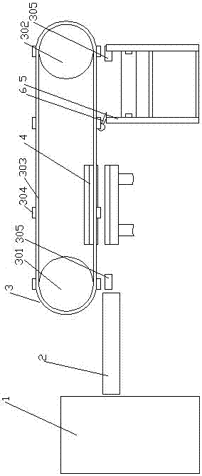
[0023] Such as Figure 1-10As shown, a packaging box die-cutting machine includes a feeding mechanism, a conveying mechanism, a die-cutting mechanism, and a discharging mechanism arranged in sequence along the input to output direction, and grippers are arranged between the die-cutting mechanism and the discharging mechanism. The gripper row mechanism includes a driving wheel and a driven wheel. The driving wheel and the driven wheel are driven by a chain. The chain is evenly distributed with a gripper row. The lower part of the driving wheel and the lower part of the driven wheel are equipped with open teeth device, the die-cutting mechanism is located at the lower rear side of the driving wheel, and the unloading mechanism is located under the teeth opening device at the lower part of the driven wheel.

[0024] In this embodiment, the feeding mechanism includes a horizontal working platform for placing the film stack, a frame is arranged above the working platform, and a fil...


PUM


Abstract

The invention relates to a die-cutting machine of a packaging box. The die-cutting machine comprises a feeding mechanism, a conveying mechanism, a die-cutting mechanism and a discharging mechanism which are sequentially arranged from the input direction to the output direction. A gripper row mechanism is arranged between the die-cutting mechanism and the discharging mechanism in a penetrating manner and comprises a driving wheel and a driven wheel. The driving wheel and the driven wheel are in transmission through a chain. Gripper rows are evenly distributed on the chain. The lower portion of the driving wheel and the lower portion of the driven wheel are each provided with a gripper opening device. The die-cutting mechanism is located on the lower rear side of the driving wheel. The discharging mechanism is located below the gripper opening device on the lower portion of the driven wheel. The die-cutting machine is simple in structure, suitable for die-cutting machining of membranes, stable in conveying, good in die-cutting effect and high in machining efficiency.

Description

technical field [0001] The invention relates to a packaging box die-cutting machine. Background technique [0002] The existing packaging box die-cutting machine has the following problems. First, the film on the film stack often has the problem of wrinkling and the film on the film stack being scattered and irregular during the forward feeding and conveying process, and often There are multiple sheets of film adhered and overlapped together for feeding, which affects the processing efficiency and processing quality; second, the feeding and conveying mechanism of the packaging box die-cutting machine, when the film is fed forward and conveyed, the film often appears wrinkled 1. Too much pressing pressure will cause the film to be damaged or the film will be over-stretched and deformed. Too little pressing pressure will cause some parts of the film to stay and cause wrinkles and damage, and the film transportation will be incoherent and unstable, which will affect the process...

Claims


Application Information

Patent Timeline
Patent Type & Authority Patents(China)
IPC IPC(8): B26F1/38B26D7/02B26D7/06B26D7/32B26D7/10
CPCB26D7/018B26D7/025B26D7/0625B26D7/0675B26D7/10B26D7/32B26D2007/082B26D2007/322B26F1/38B26F2001/3873
Inventor 周宗佑
Owner FUJIAN YINGHAO CULTURAL & CREATIVE CO LTD
Learn More