Polarizing plate and manufacturing method thereof
A manufacturing method and technology of polarizing plates, applied in manufacturing tools, polarizing elements, grinding/polishing equipment, etc., can solve problems such as reducing display performance, reducing polarizing plate quality, and reducing dimensional accuracy
- Summary
- Abstract
- Description
- Claims
- Application Information
AI Technical Summary
Problems solved by technology
Method used
Image
Examples
Embodiment 1
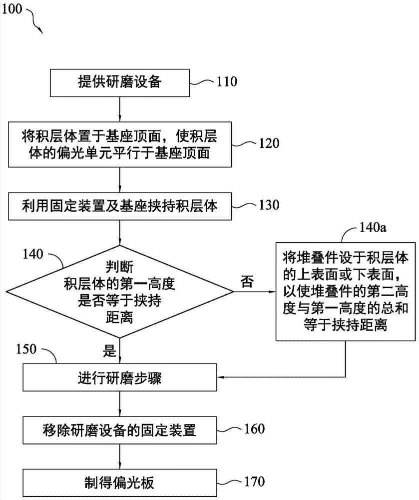
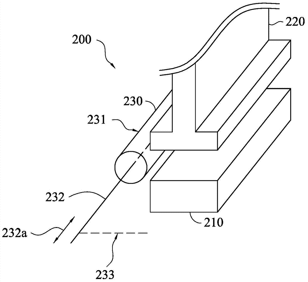
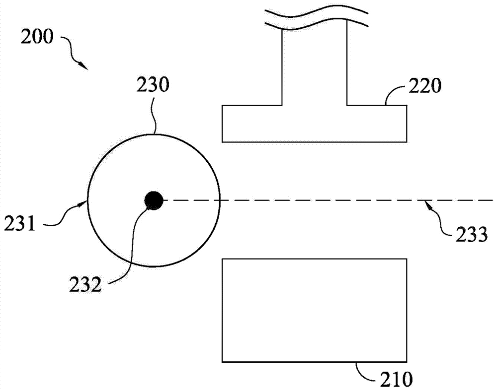
[0092] Please also refer to Figure 3a to Figure 3c , the laminated body 300 is first placed on the base 210, and the laminated body 300 is clamped by the fixing device 220 and the base 210, wherein the laminated body 300 includes a plurality of polarizing units 310, and these polarizing units 310 each include at least one An adhesive film 310b is layered, and the adhesive film 310b is disposed between the optical film 310a and the release layer 310c. In this embodiment, the first height H1 of the laminated body 300 is equal to the holding distance D between the fixing device 220 and the base 210 .
[0093] Then, the laminated body 300 was ground with the grinding surface 231 of the grinding device 230 at a cutting angle θ of 70°. After the grinding step, the polarizing plate of Example 1 can be obtained, and its structure is as follows Figure 5a shown. The obtained polarizing plate was evaluated by the following evaluation methods, and the evaluation results are shown in ...
Embodiment 2 to Embodiment 6 and comparative example 1 to comparative example 4
[0095] Example 2 to Example 6 and Comparative Example 1 to Comparative Example 4 used the same method as Example 1 to prepare polarizing plates. The difference is that Example 2 to Example 6 and Comparative Example 1 to Comparative Example 4 use different cutting angles to polish laminates 300 with different structures, wherein when the polarizing unit 310 includes two layers of adhesive films, these adhesive films are respectively It is arranged on both sides of the optical film, and in the adhesive film, there is a release layer on the other side away from the optical film. The structure diagram after its manufacture is as follows Figure 5b shown. The conditions and evaluation results of Example 2 to Example 6 and Comparative Example 1 to Comparative Example 4 are shown in Table 1, and will not be repeated here.
[0096] Evaluation method
[0097] 1. Grinding quality
[0098] For the polarizers prepared in Examples 1 to 6 and Comparative Examples 1 to 4, the grinding qua...
PUM
 Abstract
Description
Claims
Application Information
 - R&D
- Intellectual Property
- Life Sciences
- Materials
- Tech Scout
- Unparalleled Data Quality
- Higher Quality Content
- 60% Fewer Hallucinations
Browse by: Latest US Patents, China's latest patents, Technical Efficacy Thesaurus, Application Domain, Technology Topic, Popular Technical Reports.
© 2025 PatSnap. All rights reserved.Legal|Privacy policy|Modern Slavery Act Transparency Statement|Sitemap|About US| Contact US: help@patsnap.com


