Gas purifier and method of operation
A technology for gas purifiers and shells, which is applied to chemical instruments and methods, separation methods, and separation of dispersed particles. It can solve problems that affect filtration performance, blockage of filter cotton or activated carbon pores, and achieve the effect of improving the effect.
- Summary
- Abstract
- Description
- Claims
- Application Information
AI Technical Summary
Problems solved by technology
Method used
Image
Examples
Embodiment 1
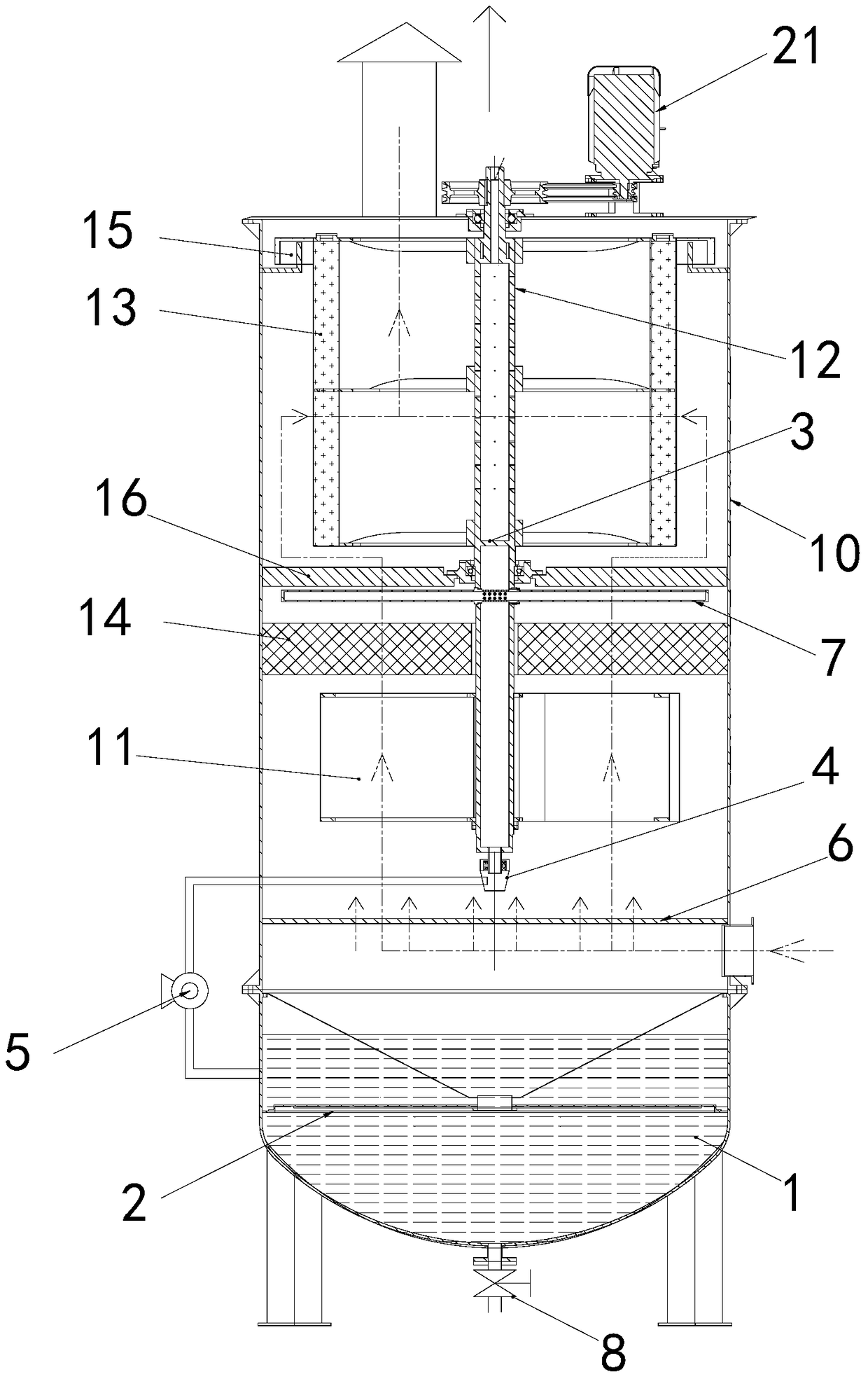
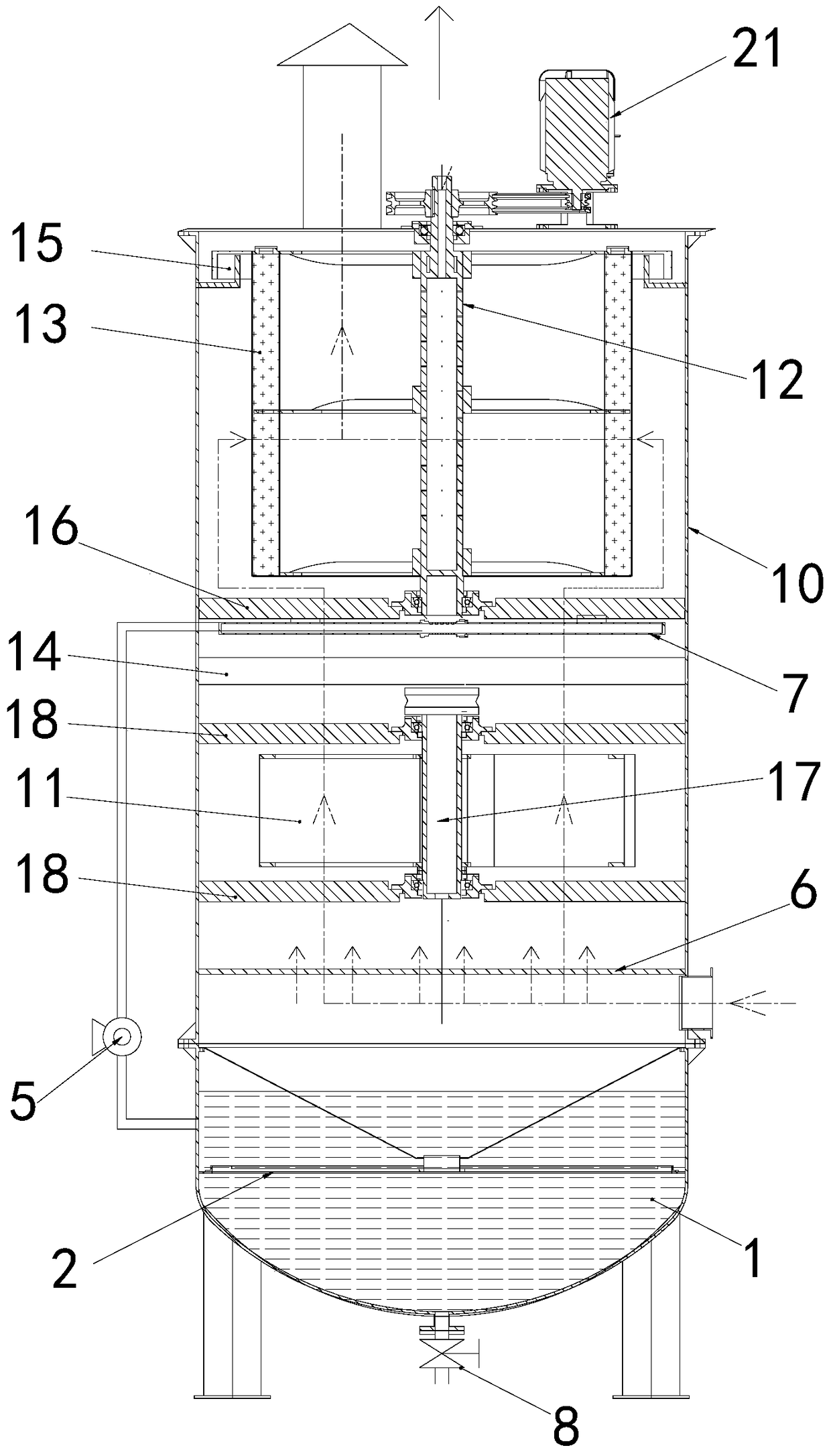
[0021] Such as figure 1 As shown, the gas purifier of the present invention includes: a water storage tank 1, a filter layer 2, a partition 3, a rotary joint 4, a water pump 5, a gas distribution plate 6, a shower 7, a drain valve 8, a high-pressure water spray pipe 9, A closed casing 10, a filter blade 11, a hollow shaft 12, a filter cartridge 13, a primary filter material layer 14, a sealing mechanism 15, a bracket 16, and a motor 21.
[0022] The housing 10 is cylindrical, and the hollow shaft 12 arranged longitudinally is rotatably fitted in the housing 10 and arranged concentrically with the housing 10. The hollow shaft 12 is fixedly sleeved with a filter cartridge 13 for filtering gas, and the filter The bottom of the cylinder 13 is closed and the top end is open. In the filter cartridge 13, a plurality of water spray holes 14 are distributed on the walls around the hollow shaft 12 (this constitutes a water spray device), and the top end of the hollow shaft is used to c...
Embodiment 2
[0033] On the basis of Embodiment 1, there are the following modifications in this embodiment:
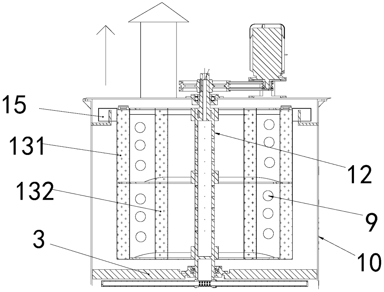
[0034] Such as figure 2 , the filter cartridge 13 includes a plurality of cylinders with the same central axis and arranged alternately, only the outermost cylinder 131 and the top inner wall of the housing 10 are rotated and sealed by the sealing mechanism 15, and the walls of each cylinder The diameter of the micropores on the top gradually becomes smaller in the direction of gas travel; a coiled high-pressure water spray pipe 9 is provided in the gap between adjacent cylinders, which is used to spray water on the inner wall of the corresponding cylinder; The bottom end is closed, and the top of the adjacent cylinder is sealed and connected; only the top port of the innermost cylinder 132 communicates with the exhaust port on the top wall of the housing 10; the coiled high-pressure water spray pipe 9 is connected to all The water inlet of the hollow shaft 12 is connected.
Embodiment 3
[0036] A working method of the gas purifier described in the above embodiment 1 or 2, comprising: the gas to be purified is input into the housing 10 from the air inlet, enters the filter cartridge radially from the outside of the filter cartridge 13 under the action of air pressure, Part of the particles or oil in the gas is adhered to the outer wall of the filter cartridge 13, and the water spray hole on the hollow shaft sprays water to the inner wall of the filter cartridge at regular intervals or all the time;
[0037] At the same time, the hollow shaft drives the filter cartridge to rotate, so that the water in the filter cartridge passes through the micropores on the wall of the filter cartridge under centrifugal force, reaches the outer wall of the filter cartridge, and scours the outer wall of the filter cartridge particulate matter on.
[0038] The water in the upper box at the bottom of the housing 10 is sent to the shower 7 in the housing 10 through the water pump 5...
PUM
 Abstract
Description
Claims
Application Information
 - R&D Engineer
- R&D Manager
- IP Professional
- Industry Leading Data Capabilities
- Powerful AI technology
- Patent DNA Extraction
Browse by: Latest US Patents, China's latest patents, Technical Efficacy Thesaurus, Application Domain, Technology Topic, Popular Technical Reports.
© 2024 PatSnap. All rights reserved.Legal|Privacy policy|Modern Slavery Act Transparency Statement|Sitemap|About US| Contact US: help@patsnap.com


