Mobile terminal positioning method, base station and node
A technology for mobile terminals and positioning nodes, which is applied in the field of communication and can solve the problems of inability to locate mobile terminals and base stations to distinguish positioning signals.
- Summary
- Abstract
- Description
- Claims
- Application Information
AI Technical Summary
Problems solved by technology
Method used
Image
Examples
Embodiment 1
[0116] figure 1 Shown is a flow chart of a mobile terminal positioning method according to an embodiment of the present invention, and the method is used in a base station. In this embodiment, the mobile terminal is positioned through uplink data. Such as figure 1 As shown, the method includes:
[0117] In step 101, each node is allocated a specified time period for receiving the uplink reference signal.
[0118] Step 102, receiving uplink reference signals received within a specified time period forwarded by each node.
[0119] In the embodiment of the present invention, after the node receives the uplink reference signal, it can forward the uplink reference signal within the received time period, or delay the forwarding, for example, receive it in the N time period, and forward it to the base station in the N time period , may also be delayed until the N+5th time period and forwarded to the base station.
[0120] The delay time for each node to delay forwarding the upli...
Embodiment 2
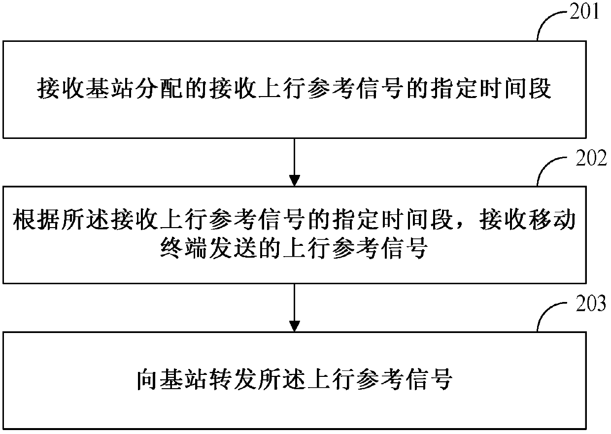
[0141] figure 2 Shown is a flowchart of a mobile terminal positioning method according to an embodiment of the present invention, and the method is used for a node. Such as figure 2 As shown, the method includes:
[0142] Step 201, receiving a designated time period allocated by a base station for receiving an uplink reference signal.
[0143] Step 202: Receive the uplink reference signal sent by the mobile terminal according to the specified time period for receiving the uplink reference signal.
[0144] Step 203, forwarding the uplink reference signal to the base station, so that the base station obtains the power of the uplink reference signal or the signal-to-noise ratio of the uplink reference signal, and selects the time period corresponding to the uplink reference signal with the largest power or the largest signal-to-noise ratio As a positioning time period, a corresponding positioning node is obtained according to the specified time period for receiving the uplin...
Embodiment 3
[0150] image 3 Shown is a flow chart of a mobile terminal positioning method according to an embodiment of the present invention, the method comprising:
[0151] In step 301, the base station assigns each node a specified time period for receiving the uplink reference signal, and sends a synchronization command to each node.
[0152] Step 302, the node synchronizes with the time of the base station according to the synchronization command.
[0153] Step 303, the base station sends an uplink signal configuration command and power control rules to the mobile terminal.
[0154] Step 304, the mobile terminal sends the uplink reference signal to all nodes according to the uplink signal configuration command and the power control rule, and keeps the power of the sent uplink reference signal consistent.
[0155] Step 305 , according to the specified time period for receiving the uplink reference signal, the node only receives and forwards the uplink reference signal broadcast by t...
PUM
 Abstract
Description
Claims
Application Information
 - R&D
- Intellectual Property
- Life Sciences
- Materials
- Tech Scout
- Unparalleled Data Quality
- Higher Quality Content
- 60% Fewer Hallucinations
Browse by: Latest US Patents, China's latest patents, Technical Efficacy Thesaurus, Application Domain, Technology Topic, Popular Technical Reports.
© 2025 PatSnap. All rights reserved.Legal|Privacy policy|Modern Slavery Act Transparency Statement|Sitemap|About US| Contact US: help@patsnap.com


