
Evolving tyre tread

A tread, tire technology, applied in the direction of tire tread/tread pattern, heavy-duty tires, tire parts, etc.

Active Publication Date: 2016-08-03
OCIETE DE TECH MICHELIN
View PDF7 Cites 9 Cited by
  • Summary
  • Abstract
  • Description
  • Claims
  • Application Information

AI Technical Summary

Problems solved by technology

Examples of this type perform well, but require proper molding process

Method used


Image

  • Evolving tyre tread
  • Evolving tyre tread

Examples


Embodiment Construction

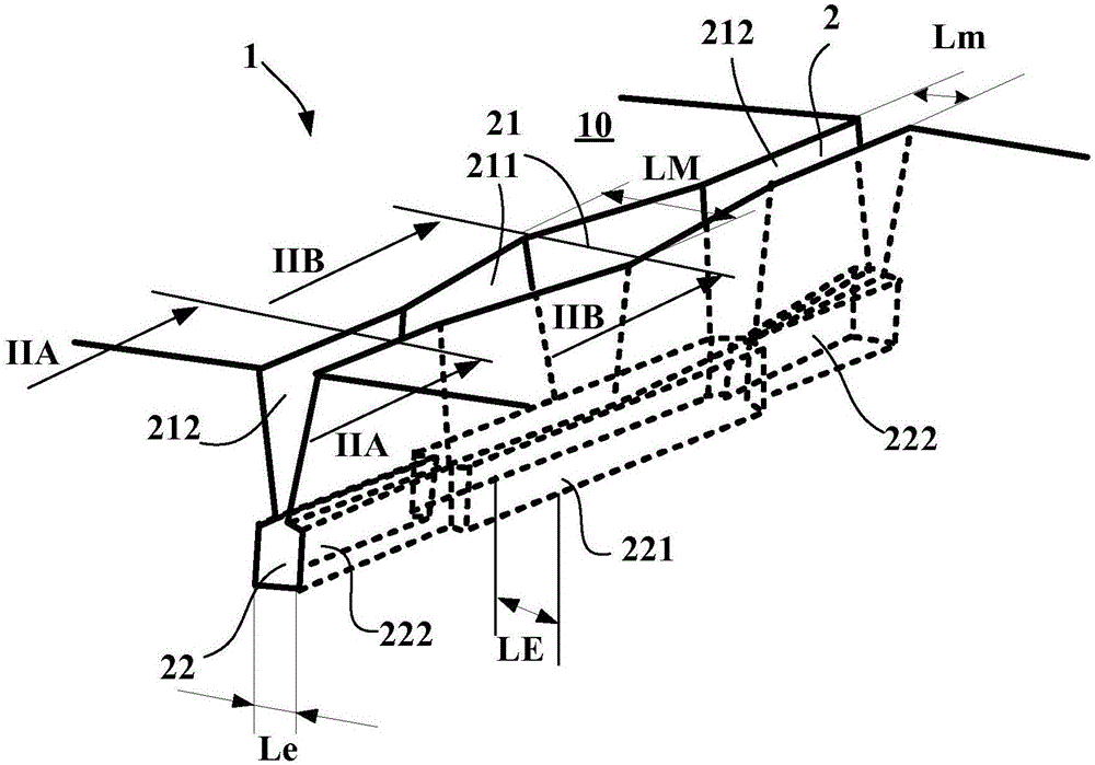
[0032] figure 1 Shown is part of a cutout according to the invention in a tread intended to be fitted to a heavy vehicle tire of size 315 / 70R22.5.

[0033] When the tread 1 is brand new (such as figure 1 ) comprises a tread surface 10 intended to contact the road during running.

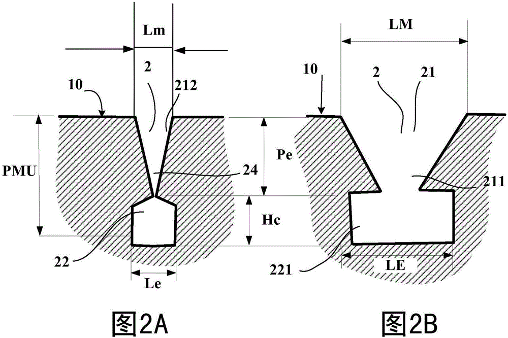
[0034]Incisions 2 oriented along the main direction lead to this tread surface 10 . This cutout 2 extends down into the thickness of the tread and to a depth greater than the maximum thickness PMU of the material to be worn away during running. This maximum thickness PMU is in this case equal to 14.5 mm. In this figure, it can be seen that the total depth of the grooves is greater than the thickness PMU of the material to be worn away, so that the good performance, especially in terms of drainage in rainy weather, is maintained until corresponding to said depth degree of wear and tear.

[0035] The cutout 2 comprises, on its outer part, ie the part radially towards the outside, a groove 21 whose...


PUM


Abstract

Heavy goods vehicle tyre tread (1) having a total thickness PMU corresponding to the thickness of material that can be worn away during driving, this tread having a tread surface (10) and comprising at least one cut (2) opening in the initial state onto the tread surface (10) in the new state, this cut (2) comprising: an external part forming a groove (21) having a mean depth Pe at most equal to 90% of the thickness PMU, and a minimum width Lm measured on the tread surface in the new state; an internal part forming the end of the cut (2) and having the form of a canal (22) of mean height Hc, the canal (22) comprising at least one narrow part (222) of maximum width Le and at least one widened part (221) of maximum width LE, each widened part (221) of the canal (22) extending into the groove (21) of the external part of the cut (2) via a widening (211) of the groove (21), this widening (211) having a maximum width LM, measured on the tread surface in the new state, at least equal to the maximum width LE of the widened part (221) of the canal.

Description

technical field [0001] The present invention relates to tire treads, more particularly to the design of the tread pattern of these treads and to tires provided with such a tread which has a permanent drainage of standing water present on the road in rainy weather The ability of these treads improves ride performance. Background technique [0002] As is known, rainy driving conditions require that water be drained between the tread of each tire and the road as quickly as possible in order to ensure contact of the tread with the road. Water that is not pushed forward of the tire flows partly along the grooves and sipes formed in the tread of the tire, regardless of whether these grooves and sipe are oriented in the circumferential direction or in the transverse direction or Orient even along an oblique direction. [0003] By incision is meant any cavity created in the tread by molding, which incision extends in the main direction and into the depth of the tread. [0004] Gr...

Claims


Application Information

Patent Timeline
Patent Type & Authority Applications(China)
IPC IPC(8): B60C11/03
CPCB60C11/0323B60C11/1307B60C2011/1338B60C2200/06
Inventor D·巴尔丹S·康邦
Owner OCIETE DE TECH MICHELIN
Learn More