
A split device

A technology of slivers and driving devices, which is applied in the direction of sustainable manufacturing/processing, electrical components, climate sustainability, etc., can solve problems such as cracks and hidden cracks, and achieve the effect of protecting silicon wafers and improving rigidity

Active Publication Date: 2018-07-31
SHANGHAI WELNEW MICRO ELECTRONICS
View PDF8 Cites 0 Cited by
  • Summary
  • Abstract
  • Description
  • Claims
  • Application Information

AI Technical Summary

Problems solved by technology

[0005] In view of the problems existing in the prior art, the purpose of the present invention is to provide a splitting device to overcome the bad defects such as cracking and hidden cracks that are easy to occur when the sheet is split manually.

Method used


Image

  • A split device
  • A split device
  • A split device

Examples


Embodiment Construction

[0072] Example embodiments will now be described more fully with reference to the accompanying drawings. Example embodiments may, however, be embodied in many forms and should not be construed as limited to the embodiments set forth herein; rather, these embodiments are provided so that this disclosure will be thorough and complete, and will fully convey the concept of example embodiments to those skilled in the art. The same reference numerals in the drawings denote the same or similar structures, and thus their repeated descriptions will be omitted.

[0073] The words expressing position and direction described in the content of the present invention are all described by taking the accompanying drawings as an example, but changes can also be made according to needs, and all changes are included in the protection scope of the present invention.

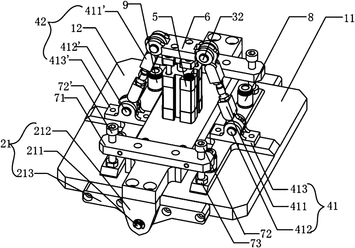
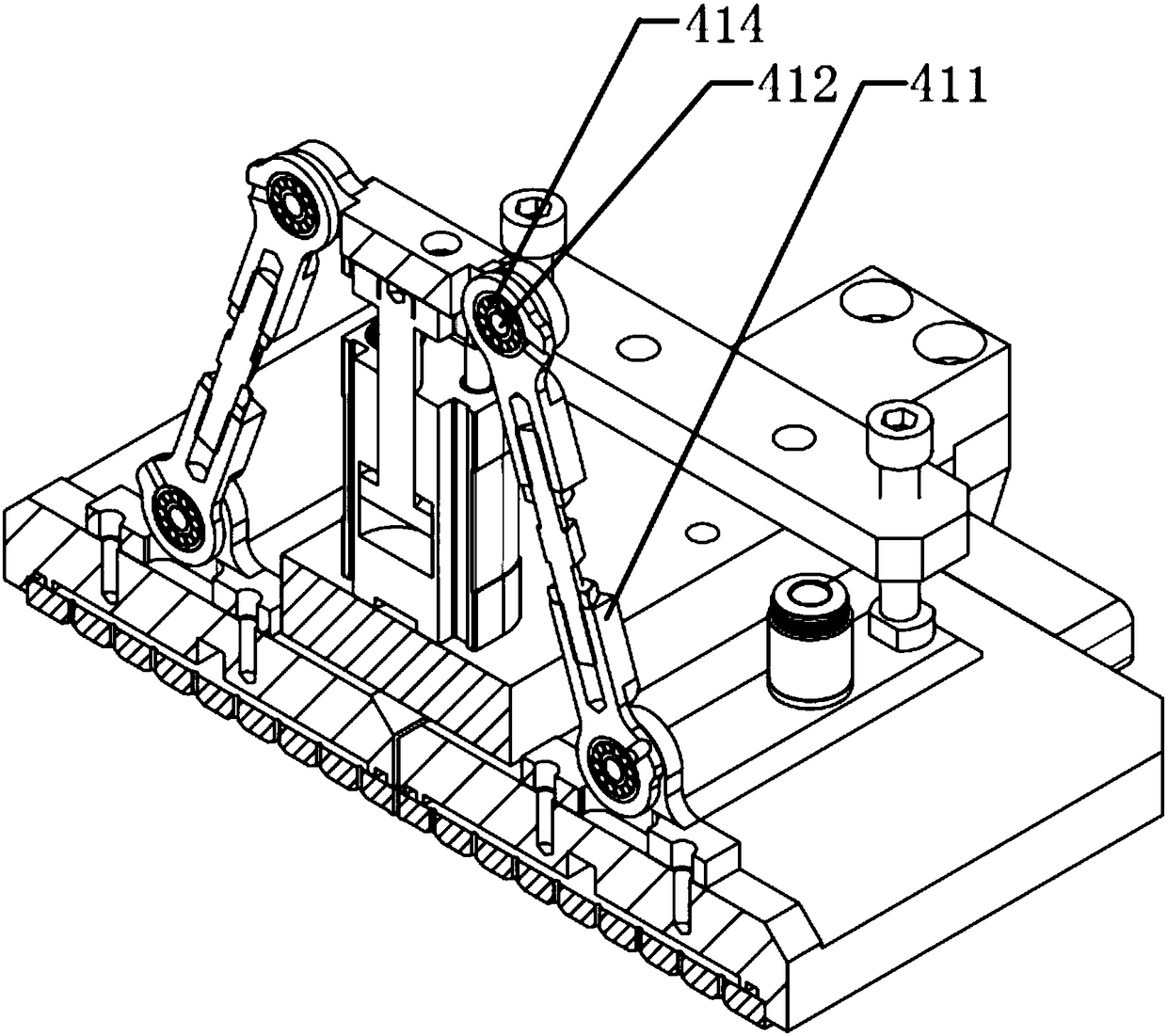
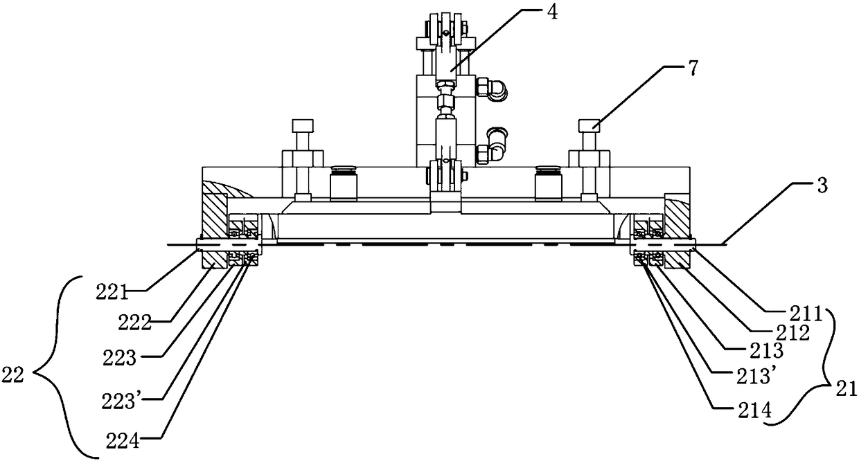
[0074] Please refer to figure 1 and figure 2, which respectively show the structural diagram of the main components of the embo...


PUM


Abstract

The invention provides a cell splitting apparatus. The cell splitting apparatus includes a cell splitting sucker and a connecting rod drive device, wherein the cell splitting sucker includes a first cell splitting sucker part and a second cell splitting sucker part which are used for sucking sheet materials; the first cell splitting sucker part and the second cell splitting sucker part are hinged to each other by encircling a common rotation axis through a hinge device; and the connecting rod drive device is arranged on the cell splitting sucker, and can drive the first cell splitting sucker part and the second cell splitting sucker part to encircle the common rotation axis to pivot relatively.

Description

technical field [0001] The invention relates to a device used in a slicing process, in particular to a splitting device. Background technique [0002] Photovoltaic solar crystalline silicon cells have developed into the heart of green new energy, and the photovoltaic industry has reached a large scale. Improving the power generation efficiency of crystalline silicon cells has become the goal pursued by the industry. [0003] The main specifications of existing solar crystalline silicon cells are: polycrystalline cells 156mm×156mm, or monocrystalline cells 125mm×125mm. In order to improve the power generation efficiency of cells and better save energy, the new cell process requires the shape of existing cells to be segmented. It is found through experiments that if a 156mm×156mm cell is split into two 156mm×78mm cells, and the two split cells are combined, the power generation efficiency will be effectively improved. [0004] The current cell splitting process is generally ...

Claims


Application Information

Patent Timeline
Patent Type & Authority Patents(China)
IPC IPC(8): H01L21/78H01L31/18
CPCH01L21/78H01L31/18Y02P70/50
Inventor 王小东肖笛胡振华黄伟黄国君肖广源
Owner SHANGHAI WELNEW MICRO ELECTRONICS
Learn More