
Optical scanning galvanometer of super high reflectivity and preparation method thereof

An optical scanning and reflectivity technology, applied in the field of scanning galvanometers, can solve problems such as affecting the scanning speed and repeat positioning accuracy of the system, changing the laser spot, affecting the quality of the galvanometer, etc., to reduce vulcanization and oxidation effects, improve flatness, The effect of improving adhesion and compactness

Active Publication Date: 2016-08-03
SANMING FOCTEK PHOTONICS INC
View PDF8 Cites 2 Cited by
  • Summary
  • Abstract
  • Description
  • Claims
  • Application Information

AI Technical Summary

Problems solved by technology

At present, the shapes of scanning galvanometers produced by most manufacturers are circular, square or special-shaped, and their weight will affect the scanning speed and repeat positioning accuracy of the system.
Existing scanning mirrors are usually gold-plated and SiO 2 Protection, because gold is soft and easy to scratch, and its adhesion is poor, the cost of coating is high
The existing dielectric film mirror has high reflectivity and good adhesion, but its reflection bandwidth is relatively narrow. For a single-wavelength laser, the reflection band is only 120nm when it is incident at 45 degrees, and the resonance angle can only reach plus or minus 10 degrees. Because of its polarization effect, it will change the shape of the laser spot and affect the quality of the galvanometer

Method used


Image

  • Optical scanning galvanometer of super high reflectivity and preparation method thereof
  • Optical scanning galvanometer of super high reflectivity and preparation method thereof
  • Optical scanning galvanometer of super high reflectivity and preparation method thereof

Examples


Embodiment Construction

[0041] The content of the present invention will be described in detail below in conjunction with the accompanying drawings and specific embodiments

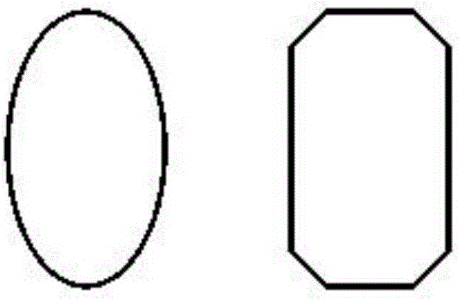
[0042] Such as figure 1 As shown, the schematic cross-sectional shape of the high-reflectivity optical scanning galvanometer of the present invention is shown. The sectional shape of the galvanometer of the present invention can be elliptical or octagonal with an axisymmetric structure.

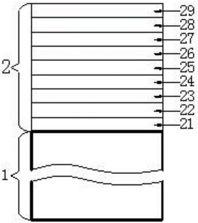
[0043] Such as figure 2 As shown, an ultra-high reflectivity optical scanning vibrating mirror, the optical scanning vibrating mirror is composed of a glass substrate layer and a high-reflection film deposited and plated on the glass substrate layer;

[0044] Below Nb 2 o 5 The film layer can also be replaced by TiO 2 、 Ta 2 o 5 or ZrO 2 .

[0045] The high-reflection film is composed of 9 film layers, and the 9 film layers are in order from near to far from the glass substrate layer: the first Al with a thickness of 98-100nm 2 o 3 T...


PUM


Abstract

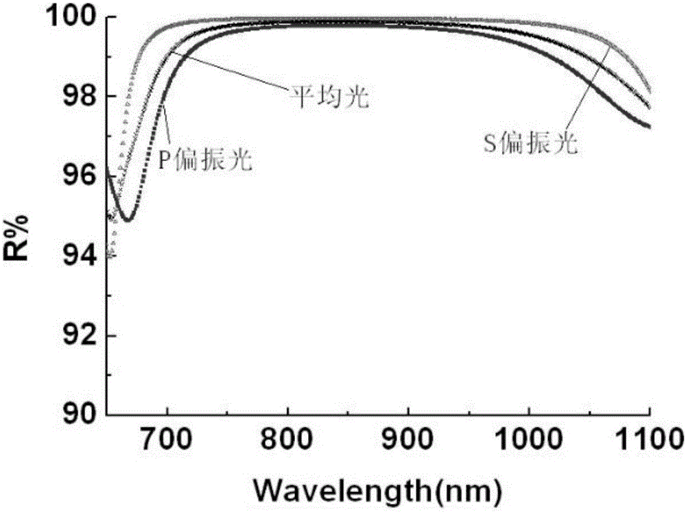
The invention relates to an optical scanning galvanometer of super high reflectivity, which is composed of a glass substrate layer and a highly-reflective film deposited and plated on the glass substrate layer. The highly-reflective film is composed of nine film layers, which are sequentially, according to the distance from the glass substrate layer from small to large, a first Al2O3 film layer, an Ag film layer, a second Al2O3 film layer, a first SiO2 film layer, a first high-refractivity material film layer, a second SiO2 film layer, a second high-refractivity material film layer, a third SiO2 film layer, and a third high-refractivity material film layer. The beneficial effects are as follows: the reflection bandwidth and resonance angle are increased greatly while the number of coating layers is reduced; the reflection bandwidth with the reflectivity higher than 99% is up to 300nm; and the effective resonance angle can be 0-80 degrees.

Description

technical field [0001] The invention relates to an ultra-high reflectance optical scanning vibrating mirror, in particular to a scanning vibrating mirror with large reflection bandwidth, large resonance angle, small polarization effect and corrosion resistance. Background technique [0002] The scanning galvanometer is an excellent vector scanning device. It is equipped with two mirrors (scanning mirrors). The reflection angle of the mirrors is controlled by a computer. These two mirrors can scan along the X-axis and Y-axis respectively to reach the laser beam. The deflection of the beam makes the laser focus point plotted with a certain power to mark on the material. At present, the shapes of scanning galvanometers produced by most manufacturers are circular, square or special-shaped, and their weight will affect the scanning speed and repeat positioning accuracy of the system. Existing scanning mirrors are usually gold-plated and SiO 2 Protection, because gold is soft an...

Claims


Application Information

Patent Timeline
IPC IPC(8): G02B26/10C23C14/30C23C14/08C23C14/10C23C14/26C23C14/18
CPCC23C14/081C23C14/10C23C14/18C23C14/26C23C14/30G02B26/101
Inventor 吴小春叶沈航
Owner SANMING FOCTEK PHOTONICS INC
Learn More