
Novel petroleum exploitation auxiliary device

A technology for oil extraction and auxiliary devices, applied in pipeline systems, mechanical equipment, gas/liquid distribution and storage, etc., can solve the problems of high oil extraction concentration, unreachable temperature, and high oil wax content, and achieve uniform heating, guaranteeing The effect of normal conveying and improving performance

Inactive Publication Date: 2016-08-03
CHENGDU KECHUANG JIASI TECH
View PDF12 Cites 17 Cited by
  • Summary
  • Abstract
  • Description
  • Claims
  • Application Information

AI Technical Summary

Problems solved by technology

In the process of oil production, it is often necessary to use production auxiliary devices to heat and reduce the viscosity of the crude oil extracted from the well to be transported to the combined station, while the mixed fluid of crude oil and water is often heated and transported at the wellhead, which often flows when it flows. Oil-water separation occurs, so the heating of the fluid in the auxiliary device is not sufficient and uniform, so that the temperature required for transportation cannot be reached; in addition, due to the high wax content of petroleum and the high oil concentration, the oil in the auxiliary device is also It is easy to produce the phenomenon of sticking and extending to blockage, which greatly affects the normal exploitation and transportation of oil, and also greatly reduces the performance of auxiliary devices

Method used


Image

  • Novel petroleum exploitation auxiliary device

Examples


Embodiment Construction

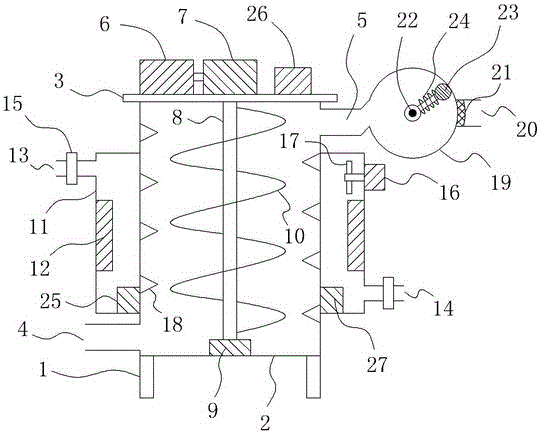
[0013] Such as figure 1 As shown, a new auxiliary device for oil extraction includes a support 1 and a cylinder 2 mounted on the support 1. A cylinder cover 3 is provided at the top of the cylinder 2, and an oil inlet is provided at the left bottom of the cylinder 2. port 4, an oil outlet 5 is provided on the top right side of the cylinder body 2, and a first motor 6 and a reducer 7 connected to the output shaft end of the first motor 6 are respectively provided on the cylinder cover 3. The output shaft end of 7 is also connected with a rotating shaft 8 through a coupling, and the rotating shaft 8 is arranged vertically downward and extends to the inside of the cylinder 2, and a bearing 9 is also provided at the inner bottom of the cylinder 2, and the rotating shaft 8 The bottom end is fixedly connected to the inner ring of the bearing 9, and a helical blade 10 is also provided on the rotating shaft 8, and a plurality of blade holes (not shown in the figure) are evenly distrib...


PUM


Abstract

The invention relates to a novel petroleum exploitation auxiliary device. The novel petroleum exploitation auxiliary device comprises a bracket, a cylinder body and a cylinder cover, wherein the bottom end of the left side of the cylinder body is provided with a petroleum inlet, and the top end of the right side of the cylinder body is provided with a petroleum outlet; a first motor and a speed reducer are arranged on the cylinder cover; the output shaft end of the speed reducer is connected with a rotating shaft; a bearing is arranged at the bottom end in the cylinder body, and the bottom end of the rotating shaft is fixedly connected with an inner ring of the bearing; a spiral blade is arranged on the rotating shaft, and blade holes are formed in the spiral blade; an annular heating cavity is arranged on the vertical outer side wall of the cylinder body, and an electric heater is arranged in the annular heating cavity; the top of the left side and the bottom of the right side, of the annular heating cavity, are separately provided with a liquid inlet and a liquid outlet, and a second motor is arranged at the top of the right side of the annular heating cavity; a plurality of mixing blades are arranged at the left end of an output shaft of the second motor; and the vertical outer side wall of the annular heating cavity is sequentially coated with a heat preservation layer, a thermal insulating layer and a wear-resistant layer. By adopting the structure, the novel petroleum exploitation auxiliary device can fully and uniformly heat petroleum and also effectively ensures the normal delivery of petroleum.

Description

technical field [0001] The invention relates to a novel auxiliary device for oil exploitation. Background technique [0002] As an important lifeline of the economy, oil has a huge impact on social development and daily life, and oil extraction and transportation have become an important link in the process of oil utilization. In the process of oil production, it is often necessary to use production auxiliary devices to heat and reduce the viscosity of the crude oil extracted from the well to be transported to the combined station, while the mixed fluid of crude oil and water is often heated and transported at the wellhead, which often flows when it flows. Oil-water separation occurs, so the heating of the fluid in the auxiliary device is not sufficient and uniform, so that the temperature required for transportation cannot be reached; in addition, due to the high wax content of petroleum and the high oil concentration, the oil in the auxiliary device is also It is easy to ...

Claims


Application Information

Patent Timeline
IPC IPC(8): F17D1/18
CPCF17D1/18
Inventor 缪家戌
Owner CHENGDU KECHUANG JIASI TECH
Learn More