Check valve

A technology of check valve and valve plate, which is applied in the direction of lifting valve, control valve, valve device, etc. It can solve the problems of insufficient pressure, poor sealing, and inability to realize elastic sealing layer, so as to prevent serious wear, improve plugging, Effect of increasing time life and utility effect

Active Publication Date: 2016-08-03
TAIZHOU AIDI XISHENGDA TUBE CO LTD
View PDF6 Cites 0 Cited by
  • Summary
  • Abstract
  • Description
  • Claims
  • Application Information

AI Technical Summary

Problems solved by technology

The sealing principle is that the valve plate rotates around the pin shaft in the valve body, and the sealing end face of the valve plate seals the inner port of the liquid inlet chamber. The main way to realize the effect of non-return is that the valve plate seals the port of the liquid inlet chamber. However, to achieve the technical effect that the valve plate seals the port of the liquid inlet chamber, it is mainly due to the weight of the valve disc itself that the valve disc is positioned at the port of the liquid inlet chamber in the bottom of the rocker, and then through the liquid outlet chamber The pressure of the liquid flowing in the opposite direction realizes the elastic sealing layer on the valve plate to seal the port of the liquid inlet chamber, but if the pressure of the liquid flowing in the reverse direction from the liquid outlet chamber is low, the pressure on the valve plate will be insufficient , it is impossible to realize the elastic sealing layer to seal the port of the liquid inlet chamber, resulting in liquid leakage
[0003] To solve this problem, in the prior art, a protruding elastic sealing body is arranged on the port side of the valve plate relative to the liquid inlet chamber, and the sub-elastic sealing body can be automatically inserted into the liquid inlet after the valve plate rotates toward the liquid inlet chamber. However, after a period of use, the elastic sealing body often wears too quickly due to excessive force on one side when it is plugged into the port of the liquid inlet chamber, and eventually appears The problem of leakage due to poor sealing

Method used


Image

  • Check valve
  • Check valve
  • Check valve

Examples


Embodiment

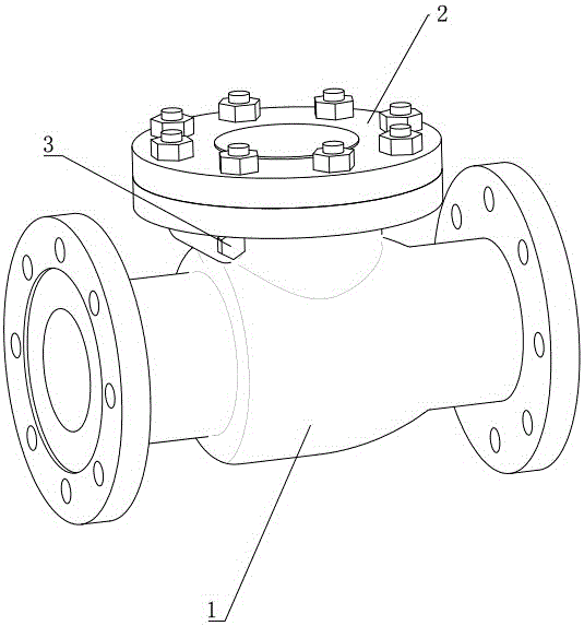
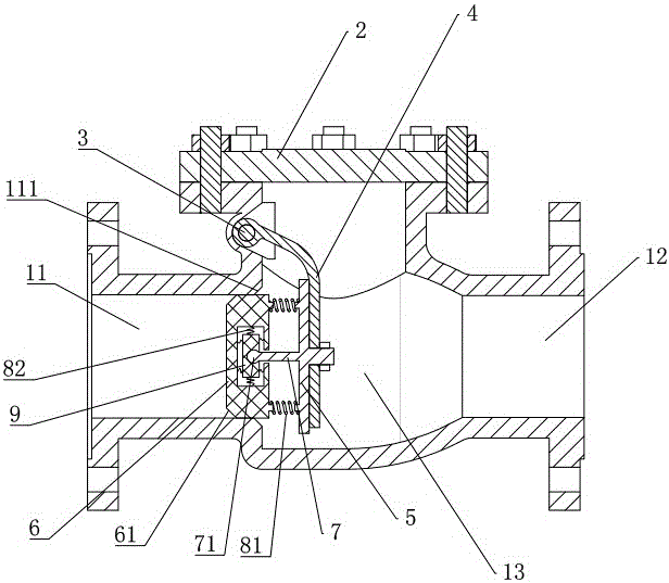
[0024] Embodiment, a kind of check valve, refer to the attached Figure 1-2 , the valve seat 1 is provided with an inlet channel 11 and an outlet channel 12, a valve cavity 13 is provided between the inlet channel 11 and the outlet channel 12, and a valve body with a flange is provided at the valve cavity 13. The valve neck, the valve neck is connected with the valve cover 2, the valve shaft 3 is hinged at the valve neck, the valve shaft 3 is pivotally connected with the rocker arm 4, and the valve plate 5 is fixed on the rocker arm 4;

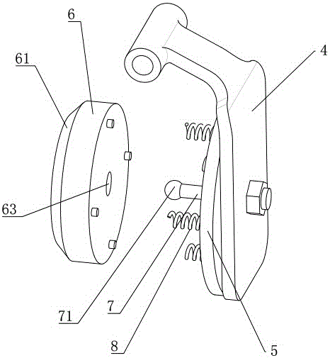
[0025] See attached image 3 and 4 combined with figure 2 , is an exploded view of the connection between the valve plate 5 and the elastic sealing body 6, the valve plate 5 is fixed with a support rod, and after the support rod passes through the relief hole 63 provided on the elastic sealing body 6, the floating block 9 is arranged in the floating cavity 62 , a ball head 71 is provided at the end of the support rod, and a ball seat cavit...


PUM


Abstract

The invention discloses a check valve which comprises a valve seat provided by with an inflow channel and an outflow channel, wherein a valve shaft is hinged onto the valve seat; a rocker arm is in pin joint with the valve shaft; and a valve plate is fixed on the rocker arm. The check valve is characterized in that when the valve plate swings down along with the rocker arm and reaches a vertical state, an elastic sealing body which can be squeezed into the inflow channel to form a seal is arranged at the end, relative to the inflow end, of the valve plate; the elastic sealing body is in floating connection with the valve body in both the axial direction and the radial direction of the inflow channel; and by virtue of the floating connection between the valve plate and the elastic sealing body, the elastic sealing body can be more automatically and flexibly squeezed into the inflow channel, the problem that the elastic sealing body is seriously abraded due to excessive unilateral or partial stress can be solved, the service life of the elastic sealing body can be prolonged, and the practical effect of the elastic sealing body can be improved.

Description

technical field [0001] The present invention relates to a valve body, and more particularly, it relates to a check valve. Background technique [0002] At present, the known swing-type soft-sealed check valve includes a valve body, which is provided with a liquid inlet chamber and a liquid outlet chamber that communicate with each other. The outer surface of the valve plate blocked by the liquid outlet chamber is covered with an elastic sealing layer; one end surface of the valve plate is a connection end surface for connecting with the rocker, and the other end surface is a sealing end surface. The sealing principle is that the valve plate rotates around the pin shaft in the valve body, and the sealing end face of the valve plate seals the inner port of the liquid inlet chamber. The main way to realize the effect of non-return is that the valve plate seals the port of the liquid inlet chamber. However, to achieve the technical effect that the valve plate seals the port of ...

Claims


Application Information

Patent Timeline
IPC IPC(8): F16K15/03F16K1/36
CPCF16K1/36F16K15/03
Inventor 杨思榕
Owner TAIZHOU AIDI XISHENGDA TUBE CO LTD
Why Eureka
Try Eureka