
A hydraulic fracturing perforation structure

A technology of hydraulic fracturing and pore structure, which is applied in the direction of production fluid, wellbore/well parts, earthwork drilling and production, etc. It can solve the problem that the maximum stress direction of perforation is not consistent, effective network fractures cannot be formed, and a large number of effective fractures cannot be formed by perforation. problems such as mesh seams, to achieve a good effect of increasing production and improving permeability

Inactive Publication Date: 2018-09-07
GUIZHOU UNIV
View PDF4 Cites 0 Cited by
  • Summary
  • Abstract
  • Description
  • Claims
  • Application Information

AI Technical Summary

Problems solved by technology

[0004] The technical problem to be solved by the present invention is to provide a hydraulic fracturing perforation structure to solve the problem that the perforation in the prior art cannot form a large number of effective network fractures. In conventional hydraulic fracturing, due to the crustal movement, the maximum stress of the shale layer is limited. The direction is not completely horizontal, so in perforation fracturing, the perforation and the direction of maximum stress are often inconsistent, resulting in the inability to form effective network fractures in perforation fracturing, that is, the width of the fractures cannot meet the requirements of high-efficiency penetration, and the stimulation effect Obvious issues

Method used


Image

  • A hydraulic fracturing perforation structure
  • A hydraulic fracturing perforation structure

Examples


Embodiment Construction

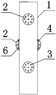
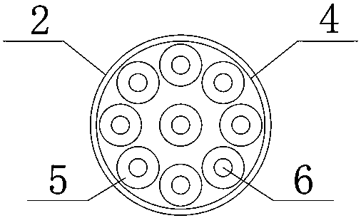
[0019] A hydraulic fracturing perforation structure comprising (see figure 1 ) Drilling wall 1, a spherical surface 2 is arranged on the drilling wall 1, and a perforation 3 is arranged on the spherical surface 2. A guide tube 6 is arranged inside the perforation 3, and one end of the guide tube 6 is connected with the pressure bearing plate 5, and the pressure bearing plate 5 is located on the bearing The inner side of the pressure surface 4, the pressure receiving surface 4 is fixed on the inner side of the spherical surface 2.

[0020] The perforations 3 are evenly arranged on the spherical surface 2, and the diameter of the perforations 3 is 8-10 mm.

[0021] The distance between the perforation 3 and the guide pipe 6 is 1-2 millimeters; ensure that the guide pipe 6 can be put into the perforation 3 smoothly.

[0022] The length of the guide tube 6 is 1-2 mm longer than the distance between the pressure bearing surface 4 and the spherical surface 2, so as to ensure that t...


PUM


Abstract

The invention discloses a hydraulic fracturing and perforating structure. The structure comprises a drill wall (1), wherein a spherical surface (2) is formed in the drill wall (1); a perforation (3) is formed in the spherical surface (2); a guide pipe (6) is arranged inside the perforation (3); one end of the guide pipe (6) is connected with a pressure-bearing piece (5); the pressure-bearing piece (5) is positioned on the inner side of a pressure-bearing surface (4); the pressure-bearing surface (4) is fixedly arranged on the inner side of the spherical surface (2). The problems in the prior art that lots of effective net gaps cannot be formed during fracturing and perforating and the perforation and the maximum stress direction are always not consistent while fracturing and perforating so as not to form effective net gaps during fracturing and perforating because the maximum stress direction of shale formation is not completely horizontal due to crustal movement, i.e., the width of cracks cannot meet the high-efficiency permeation requirement, the yield-increasing effect is not obvious and the like are solved.

Description

technical field [0001] The invention belongs to natural gas fracturing technology, in particular to a hydraulic fracturing perforation structure. Background technique [0002] Shale gas occurs in organic-rich mud shale and its interlayers. Due to the physical properties of shale gas reservoirs with low porosity and low permeability, the gas flow overflow resistance is greater than that of conventional natural gas, and there is basically no natural productivity. Fracturing is required. , shale gas can be effectively exploited. [0003] In conventional hydraulic fracturing, the perforation pressure starts along the preferential fracture plane and propagates to the rock formation, that is, along the path of least resistance. The least resistance is caused by the difference in the direction and magnitude of the ground stress. In most cases, the vertical direction of maximum stress. When the direction of the perforation is inconsistent with the direction of the maximum stress i...

Claims


Application Information

Patent Timeline
Patent Type & Authority Patents(China)
IPC IPC(8): E21B43/26E21B43/11
CPCE21B43/11E21B43/26
Inventor 张义平杨梓梁严鸿海
Owner GUIZHOU UNIV
Learn More