
Method for prefabricating box girder adjustable reinforcement cage binding jig frame through stub matching method

A technology of steel bar binding and short-line matching, which is applied in the direction of erecting/assembling bridges, bridges, bridge construction, etc., to achieve the effects of long length, avoiding heavy work, and high-altitude risks

Active Publication Date: 2016-08-03
CCCC SECOND HARBOR ENG
View PDF5 Cites 6 Cited by
  • Summary
  • Abstract
  • Description
  • Claims
  • Application Information

AI Technical Summary

Problems solved by technology

[0003] The box girder reinforcement frame design for the above projects all adopts an integral steel frame frame with equal cross-section, that is, it is directly bound on the steel frame frame in the order of bottom plate steel bar, web steel bar, top plate steel bar and wing plate steel bar. The cage is integrally formed at one time, which is not suitable for the binding of steel cages for large-span, tall, and variable-section box girders

Method used


Image

  • Method for prefabricating box girder adjustable reinforcement cage binding jig frame through stub matching method
  • Method for prefabricating box girder adjustable reinforcement cage binding jig frame through stub matching method
  • Method for prefabricating box girder adjustable reinforcement cage binding jig frame through stub matching method

Examples


Embodiment Construction

[0041] The present invention will be further described in detail below in conjunction with the accompanying drawings, so that those skilled in the art can implement it with reference to the description.

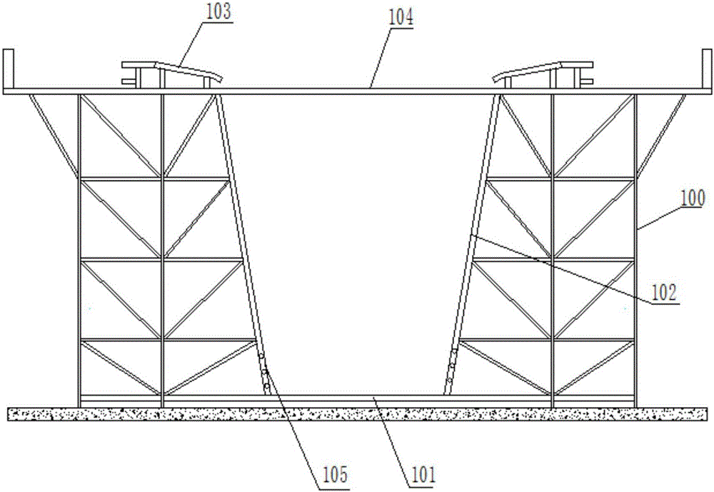
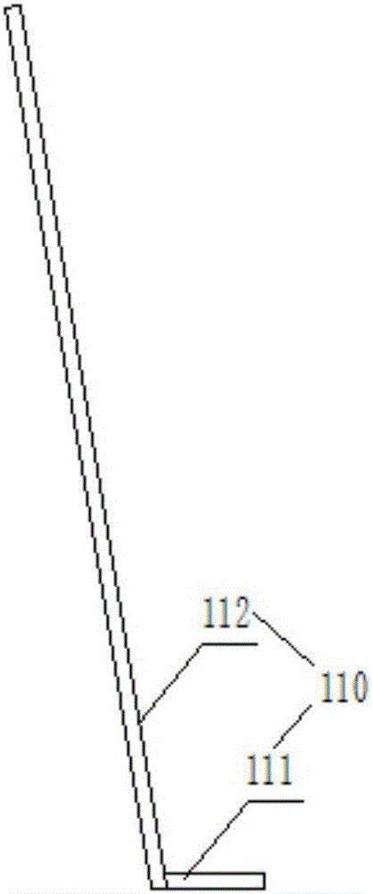
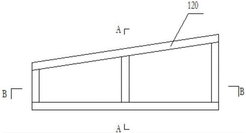
[0042] Such as Figure 1 to Figure 12 As shown, the present invention provides a method for prefabricating a box girder with an adjustable steel cage binding tire frame by a short-line matching method, which is used for prefabricating a box girder with a high height on the main tire frame 100, and the bottom plate, web plate, and roof plate have variable cross-sections. Steel cage tire frame, the steel cage bound on the main tire frame 100 corresponds to the box girder produced on the corresponding prefabricated pedestal.

[0043] The Hong Kong section of the Hong Kong-Zhuhai-Macao Bridge has a bridge span of 25 girders. From the first to the 25th girder, the height and span differ greatly. 5 tying stands, that is, 100 of 5 main tire frames will be constructed.

[0044] The r...


PUM


Abstract

The invention discloses a method for prefabricating a box girder adjustable reinforcement cage binding jig frame through a stub matching method. The method includes the steps that firstly, the body jig frame is established, wherein the body jig frame comprises a horizontal jig frame body, web jig frame bodies on the two sides, wing plate jig frame bodies on the two sides and a top board jig frame body; secondly, two pieces of first structural steel are arranged on the front side and the rear side of the body jig frame in the horizontal direction; thirdly, after web reinforcing steel bar binding jig frame bodies on the two sides are lifted out of the body jig frame, supporting frames are installed on the web reinforcing steel bar binding jig frame bodies, web reinforcing steel bars are bound, and the web reinforcing steel bar binding jig frame bodies are then lifted into the body jig frame and located and then are provided with multiple pieces of second structural steel; fourthly, the top board jig frame body is provided with four top inner cavity moving blocks which are symmetric front and back and symmetric left and right, and the top inner cavity moving blocks are detachably connected with the top board jig frame body; and fifthly, remaining reinforcing steel bars are bound. By the adoption of the method, through design of the adjustable spliced and combined type reinforcement cage binding jig frame, the reinforcing steel bar binding quality is guaranteed, the construction cost is saved, the upper air operation risks are reduced, and the construction effect is guaranteed.

Description

technical field [0001] The invention relates to a steel cage binding tire frame. More specifically, the present invention relates to a method for binding a tire frame with a prefabricated box girder adjustable reinforcement cage by a short-line matching method. Background technique [0002] At present, short-term matching method prefabrication is widely used in the United States, Europe, Japan, Southeast Asia and Hong Kong of my country, such as Hong Kong Stonecutters Bridge, T9 trunk line, etc. In recent years, there are more and more applications in mainland China, such as the Sutong Yangtze River Highway Bridge, Xiamen Jimei Bridge, Shanghai Chongqi Bridge, Nanjing Fourth Bridge, Jiashao Bridge and Xiamen-Zhangzhou Cross-sea Bridge and other projects. [0003] The box girder reinforcement frame design for the above projects all adopts an integral steel frame frame with equal cross-section, that is, it is directly bound on the steel frame frame in the order of bottom plat...

Claims


Application Information

Patent Timeline
Patent Type & Authority Applications(China)
IPC IPC(8): E01D21/00
CPCE01D21/00
Inventor 汪存书邹晖胡长兵陈禹王运发
Owner CCCC SECOND HARBOR ENG
Learn More