
Swing sprayer adjustable in spraying area

An adjustable sprinkler technology, which is applied in the direction of spraying devices, spraying devices, and spraying devices with movable outlets, can solve the problems of complicated structural design of swinging sprinklers, inability to adjust the spraying area, and limited use of functions, etc., to achieve production Low cost, easy to use, and flexible adjustment and operation

Inactive Publication Date: 2016-08-03
NINGBO DAYE GARDEN IND
View PDF5 Cites 13 Cited by
  • Summary
  • Abstract
  • Description
  • Claims
  • Application Information

AI Technical Summary

Problems solved by technology

A common swinging sprinkler is shown in the "Garden Spraying Device" with the published Chinese Patent No. 200720184467.1. Its structure is mainly composed of a base, a spraying assembly installed on the base, and a swinging gear box that drives the spraying assembly to swing. The spraying area of ​​this swinging sprinkler cannot be adjusted, and the use function is subject to certain restrictions.
At present, there is a swing sprinkler on the market that is equipped with a regulating valve to adjust the spraying range. When in use, the spraying range can be controlled according to the size of the spraying area. Although this swing sprinkler with adjustable spraying area meets the needs of users in various occasions It is necessary, but configuring one more regulating valve on the swinging sprinkler will not only make the structure design of the swinging sprinkler more complicated, but also increase the production cost. Can roughly grasp the spraying range, which also brings some inconvenience to the use

Method used


Image

  • Swing sprayer adjustable in spraying area
  • Swing sprayer adjustable in spraying area
  • Swing sprayer adjustable in spraying area

Examples


Embodiment Construction

[0019] The embodiments of the present invention will be described in detail below according to the above-mentioned drawings.

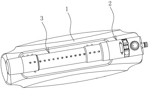
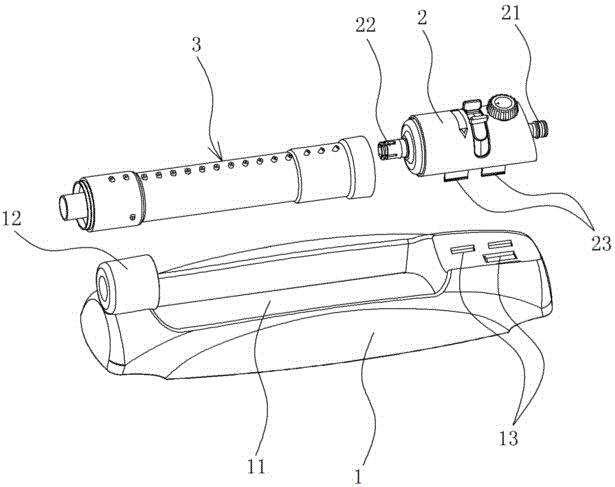
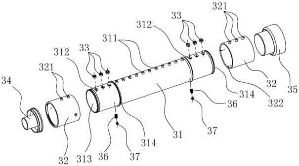
[0020] Such as Figure 1~Figure 3 As shown, 1. Base, 11. Groove, 12. Shaft seat, 13. Clamping hole, 2. Swing gear box, 21. Water inlet, 22. Water outlet, 23. Elastic clamp, 3. Sprinkler assembly , 31. Nozzle pipe, 311. Fixed nozzle hole, 312. Water hole, 313. Water cavity, 314. Shoulder, 32. Adjusting spray sleeve, 321. Adjusting nozzle hole, 322. Positioning groove, 33. Sealing gasket, 34. plug shaft, 35. connecting sleeve, 36. spring, 37. positioning beads.

[0021] Oscillating sprinklers with adjustable spraying area, such as figure 1 , figure 2 As shown, it is a jet principle that uses water pressure to swing the sprayed water flow left and right within a range of 90 degrees to form a covered spraying area, which is convenient for watering and maintenance of gardens, nurseries, lawns, etc., or building roofs Cooling, or maintenance of road con...


PUM


Abstract

The invention discloses a swing sprayer adjustable in spraying area and relates to a garden irrigation tool, and by the adoption of the garden irrigation tool, the sprayed water flow is swung through the jet flow principle of water flow pressure, and accordingly spraying area is formed. The swing sprayer comprises a base, a swing gearbox, a spraying assembly and the like. The swing sprayer is characterized in that the ends of a spray pipe of the spraying assembly are provided with water through holes communicating with a water cavity in the spray pipe, and adjusting spray sleeves, wherein the adjusting spray sleeves are rotatably sleeved with the ends of the spray pipe and can seal the water through holes in the spray pipe; a plurality of rows of adjusting spray nozzles with different numbers are formed in the adjusting spray sleeves; and the adjusting spray nozzles communicate with the water through holes sequentially and selectively under the rotation action of the adjusting spray sleeves. In this way, when original fixed spray nozzles in the spray pipe and the adjustable adjusting spray nozzles in the ends of the spray pipe are combined to use, the whole swing sprayer has a function of controlling and adjusting the spraying area; and the improved swing sprayer has the advantages of being simple in structural design, flexible in adjustment operation, convenient to use, capable of controlling adjustment for spraying area accurately, low in production cost and the like.

Description

technical field [0001] The invention relates to a swing sprinkler in a landscaping watering tool, in particular to a swing sprinkler with an adjustable spraying area. Background technique [0002] Oscillating sprinkler is a common landscaping watering tool. It mainly uses the jet principle of water flow pressure to swing left and right within a range of 90 degrees, so as to cover an area for spraying. It can also be used to cool down the roof of buildings, and it also has obvious effects on the maintenance of road construction and the control of dust and coal dust. A common swinging sprinkler is shown in the "Garden Spraying Device" with the published Chinese Patent No. 200720184467.1. Its structure is mainly composed of a base, a spraying assembly installed on the base, and a swinging gear box that drives the spraying assembly to swing. The spraying area of ​​this oscillating sprinkler cannot be adjusted, and the use function is subject to certain restrictions. At present...

Claims


Application Information

Patent Timeline
Patent Type & Authority Applications(China)
IPC IPC(8): B05B3/14B05B15/08A01G25/02B05B15/68
CPCA01G25/02B05B3/14B05B15/68B05B3/044B05B1/20
Inventor 黄纪风
Owner NINGBO DAYE GARDEN IND
Learn More