
Display panel and display device

A display panel, the same technology, applied in nonlinear optics, instruments, optics, etc., can solve the problems of reduced aperture ratio, influence of display panel color temperature, reduced aperture ratio of blue sub-pixels, etc., and achieve the effect of large aperture ratio

Active Publication Date: 2016-07-27
BOE TECH GRP CO LTD
View PDF5 Cites 25 Cited by
  • Summary
  • Abstract
  • Description
  • Claims
  • Application Information

AI Technical Summary

Problems solved by technology

Since the maximum diameter of the main spacer is larger than the maximum diameter of the secondary spacer, the corresponding part of the black matrix in the color filter substrate and the corresponding part of the main spacer is relatively wide, so that when the thin film transistor array substrate and the color filter substrate are boxed, The problem of poor display effect of the display panel caused by the offset of the main spacers, but this also reduces the aperture ratio of the sub-pixels at the corresponding positions in the color filter substrate
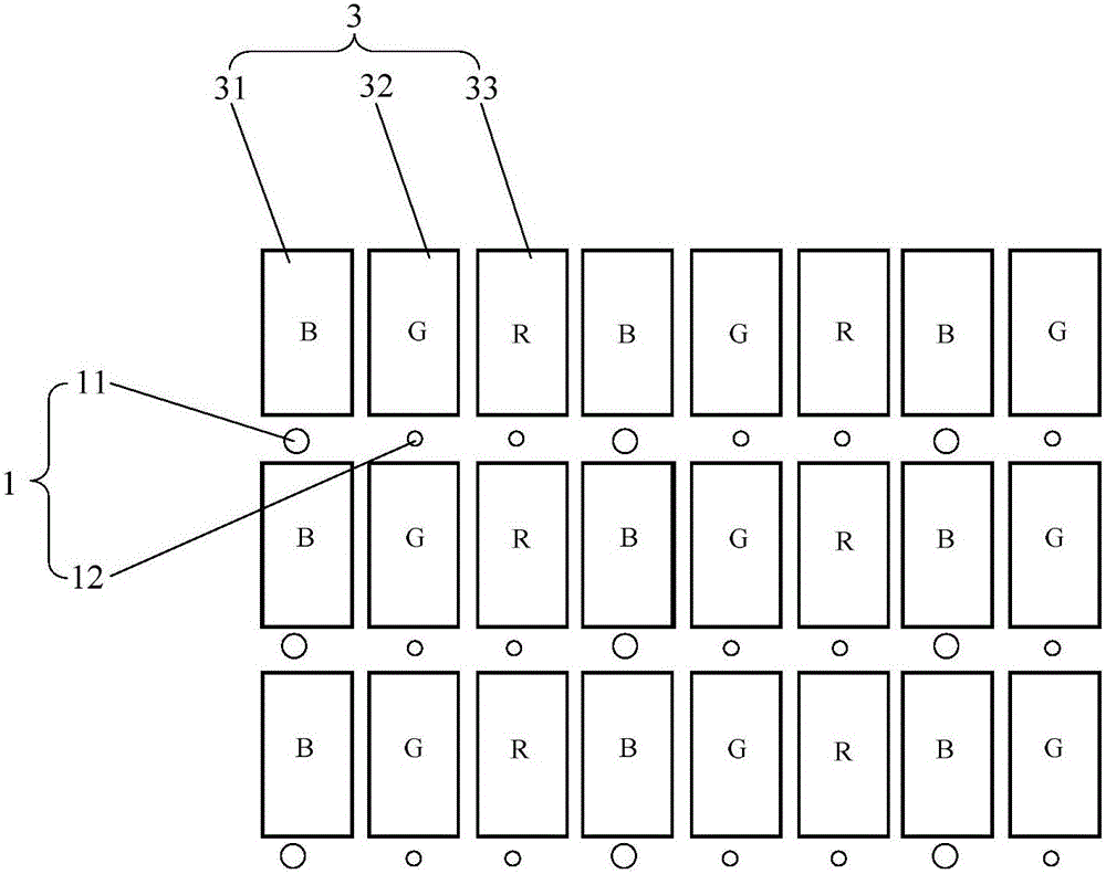
[0004] In order to solve the above problems, the existing method is to distribute the main spacers at the corresponding positions of the black matrix and the blue sub-pixels, and widen the corresponding positions of the black matrix and the blue sub-pixels; The contribution of the aperture ratio is relatively small. If the corresponding position of the black matrix and the blue sub-pixel is widened, the contribution of the blue sub-pixel to the aperture ratio of the display panel will not be greatly affected; but each blue sub-pixel in the display panel There is a one-to-one correspondence between the pixels 31 and each main spacer 11 (such as figure 1 As shown), there are more main spacers distributed on the surface of the thin film transistor array substrate or the color filter substrate, resulting in a decrease in the overall aperture ratio of the blue sub-pixel in the color filter substrate, thereby greatly affecting the aperture ratio of the display panel. Moreover, due to the reduction of the overall aperture ratio of all blue sub-pixels in the color filter substrate, the color temperature of the display panel is also affected

Method used


Image

  • Display panel and display device
  • Display panel and display device
  • Display panel and display device

Examples


Embodiment Construction

[0045]In order to further illustrate the display panel and the display device provided by the embodiments of the present invention, a detailed description will be given below in conjunction with the accompanying drawings.

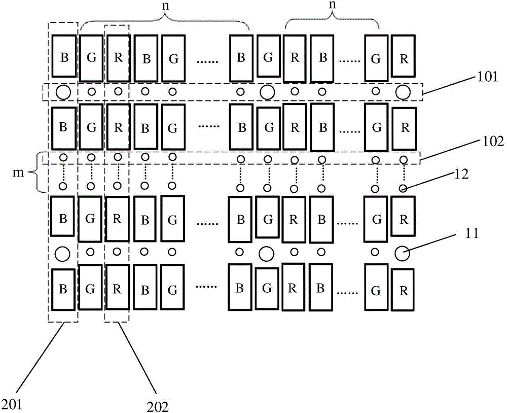
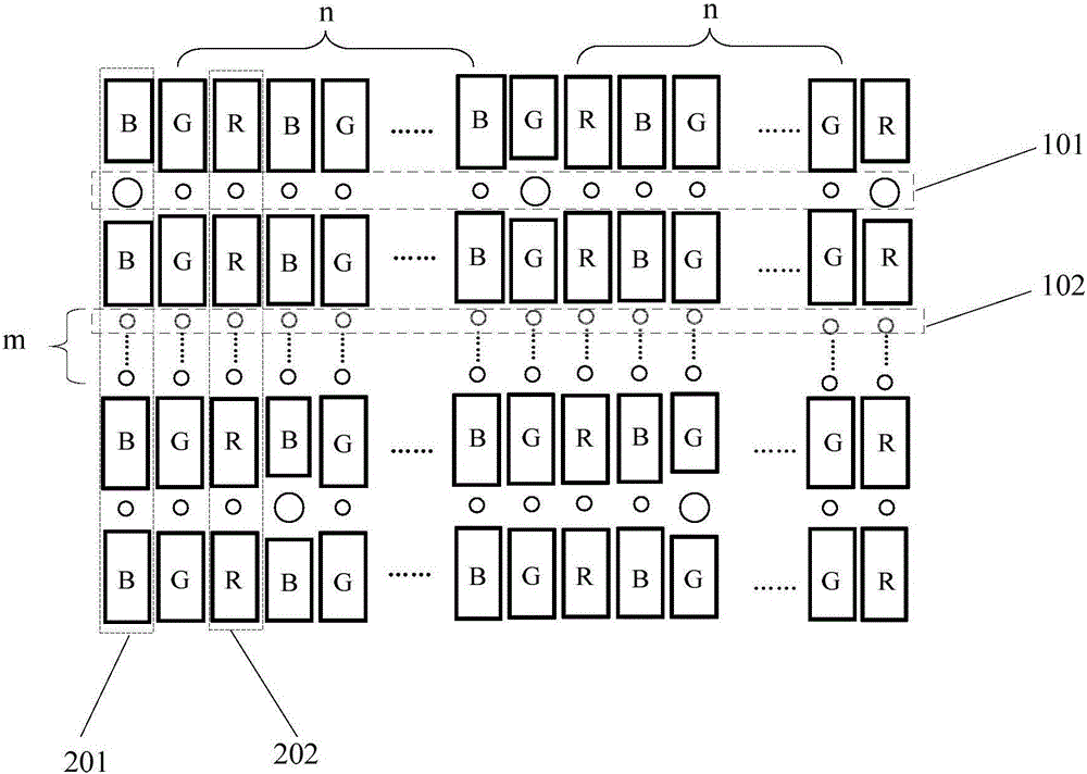
[0046] see figure 2 and image 3 , the display panel provided by the embodiment of the present invention includes: a color filter substrate and a spacer array corresponding to the black matrix and the color pixel array in the color filter substrate. In the spacer array, the spacer 1 is divided into main spacers Objects 11 and sub-spacers 12, wherein the maximum diameter of the main spacers 11 is greater than the maximum diameter of the sub-spacers 12, the spacer array includes a mixed spacer row 101 as the first type of spacers in the row direction of the black matrix. A row of spacers, and a single row of spacers as the second type of spacer row 102, specifically, the arrangement structure of the spacer array in the row direction of the black matrix incl...


PUM


Abstract

The invention discloses a display panel and a display device and relates to the technical field of liquid crystal display, aiming to increase aperture ratio of the display panel and weaken influence on color temperature.The display panel comprises a color-film substrate and a spacer array corresponding to a black matrix and a color pixel array in the color-film substrate.An arrangement structure of the spacer array in the line direction of the black matrix comprises X lines of spacers in mixed arrangement, m lines of single-row spacers are arranged between every two adjacent spacers in mixed arrangement, every line of spacers in mixed arrangement includes a main spacers, n auxiliary spacers are arranged between every two adjacent main spacers, and every line of single-row spacers includes z auxiliary spacers.The display device comprises the display panel.The display panel is used in the display device.

Description

technical field [0001] The invention relates to the technical field of liquid crystal display, in particular to a display panel and a display device. Background technique [0002] The liquid crystal panel generally includes a thin film transistor array substrate and a color filter substrate, and a liquid crystal layer arranged between the thin film transistor array substrate and the color filter substrate, and, in order to support the thin film transistor array substrate and the color filter substrate, the thin film transistor array substrate There is a certain distance between it and the color filter substrate to prevent bubbles from appearing in the liquid crystal layer of the display panel; when the liquid crystal panel is produced, it is generally between the thin film transistor array substrate and the color filter substrate and corresponds to the black matrix. Spacers are distributed, and then the thin-film transistor array substrate and the color filter substrate are ...

Claims


Application Information

Patent Timeline
IPC IPC(8): G02F1/1339
Inventor 沈武林金熙哲
Owner BOE TECH GRP CO LTD
Learn More