Power transmission line fault positioning method based on non-contact sensor

A non-contact, power transmission line technology, applied in fault locations, fault detection by conductor type, instruments, etc., can solve problems such as low positioning accuracy and low sampling rate, simplify installation, improve communication efficiency, and reduce communication data. amount of effect

Active Publication Date: 2016-07-27
YUNCHENG POWER SUPPLY COMPANY OF STATE GRID SHANXI ELECTRIC POWER +1
View PDF9 Cites 11 Cited by
  • Summary
  • Abstract
  • Description
  • Claims
  • Application Information

AI Technical Summary

Problems solved by technology

In addition, due to the low sampling rate of existing traveling wave ranging devices, most of them do not exceed 1MHz, and the positioning accuracy is also low, and the theoretical and actual ranging errors often exceed 1km

Method used


Image

  • Power transmission line fault positioning method based on non-contact sensor
  • Power transmission line fault positioning method based on non-contact sensor
  • Power transmission line fault positioning method based on non-contact sensor

Examples


Embodiment Construction

[0015] The present invention will be described in further detail below in conjunction with the accompanying drawings and specific embodiments.

[0016] The present invention proposes a transmission line fault location method based on a non-contact sensor, comprising the following steps:

[0017] S1. Install a detection device for detecting traveling wave signals every 10-15 km on the transmission line, number each detection device and mark them as A1, A2, ... Am, An, ... At.

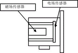
[0018] Each detection device adopted in the transmission line fault location method based on non-contact sensors of the present invention includes a sensor module, a sampling system, an A / D conversion module, and a communication module, wherein the sensor module includes 3 non-contact sensors, respectively Installed on each phase of the transmission line, the sampling system is connected to the sensor module for collecting current and voltage signals in the sensor module, the A / D conversion module is con...


PUM


Abstract

The invention provides a power transmission line fault positioning method based on a non-contact sensor. The method comprises the following steps of: S1, installing one detection device for detecting travelling wave signals every 10-15 km on a power transmission line; S2, receiving current and voltage signals in the circuit, and transmitting the current and voltage signals to a main control center through a communication module; S3, after the main control center analyzes the received data and discovers a fault traveling wave signal, finding a second fault traveling wave signal in the detection device An connected with the detection device Am corresponding to the fault traveling wave signal, and according to the fault traveling wave signal and the second fault traveling wave signal, calculating the time for a first travelling wave head to respectively arrive at the detection devices Am and An; and S4, calculating the position of a fault point. According to the invention, the power transmission line fault positioning method is high in positioning precision and can be widely applied to a high-voltage power transmission network.

Description

technical field [0001] The invention belongs to the technical field of power system protection, and in particular relates to a transmission line fault location method based on a non-contact sensor. Background technique [0002] Quickly and accurately determining the location of the fault point of the transmission line can speed up the repair of permanent faults, eliminate hidden dangers in time to avoid the recurrence of a large number of transient faults, and is of great significance to ensure the safety, stability and economic operation of the power system. [0003] At present, many methods have been proposed at home and abroad for fault location of transmission lines, mainly including impedance method, S injection method, "fault indicator" technology, feeder automation technology and traveling wave method. The impedance method is greatly affected by line impedance, load and power supply parameters. For distribution lines with multiple branches, the impedance method cannot...

Claims


Application Information

Patent Timeline
Patent Type & Authority Applications(China)
IPC IPC(8): G01R31/08
CPCG01R31/085G01R31/088Y04S10/52
Inventor 李小明杨国栋袁少锋丁孟炜卫乾虎
Owner YUNCHENG POWER SUPPLY COMPANY OF STATE GRID SHANXI ELECTRIC POWER
Why Eureka
Try Eureka