Upper-screwing lower-locking automatic insertion rod adjustable connection component

An adjustable, connecting piece technology, applied in the connection of rods, connecting members, sheet pile walls, etc., can solve the problems of work efficiency, inconvenient rotation, small space, etc., to improve work efficiency, firm connection, and improve service life. Effect

Active Publication Date: 2016-07-27
周兆弟
View PDF7 Cites 8 Cited by
  • Summary
  • Abstract
  • Description
  • Claims
  • Application Information

AI Technical Summary

Problems solved by technology

However, after careful analysis, there is also a fly in the ointment. The adjusting bolt assembly of the above-mentioned connecting piece is located under the connecting nut, and the space for the manipulator or hand tool to enter is small, and it is inconvenient to rotate, and the connecting nut needs to be fixed at the same time when rotating the adjusting bolt. Otherwise, Slippage will occur and work efficiency will be affected

Method used


Image

  • Upper-screwing lower-locking automatic insertion rod adjustable connection component
  • Upper-screwing lower-locking automatic insertion rod adjustable connection component
  • Upper-screwing lower-locking automatic insertion rod adjustable connection component

Examples


Embodiment 1

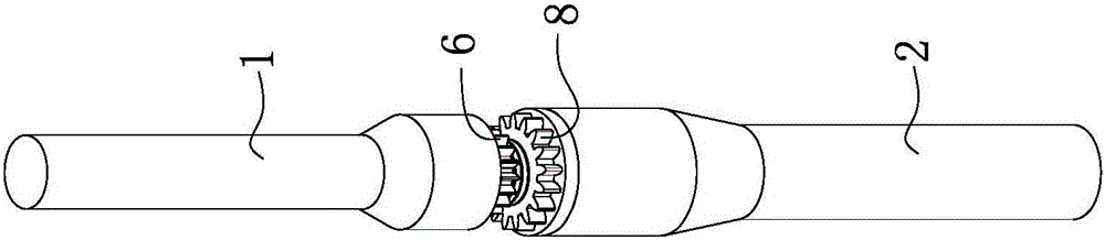
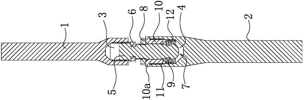
[0028] Such as figure 1 and figure 2 and image 3 As shown, a screw-on-down-lock automatic plunger adjustable connector includes an upper connecting rod 1 and a lower connecting rod 2, and the ends of the upper connecting rod 1 and the lower connecting rod 2 respectively have an upper connecting cavity 3 and The lower connection cavity 4, preferably, the outer walls of the upper connection cavity 3 and the lower connection cavity 4 are inflated, which is convenient for manufacture and connection. The upper connection cavity 3 and the lower connection cavity 4 have internal threads, and the upper connection rod 1 The inner screw is connected with a plugging rod 5, and the inner screw of the lower connecting rod 2 is connected with a clamping mechanism 7. The outer wall of the plugging rod 5 has a ring gear 6 integrally formed with the plugging rod 5. When the plugging rod 5 is inserted into When entering the clamping mechanism 7 , rotating the ring gear 6 can adjust the posi...

Embodiment 2

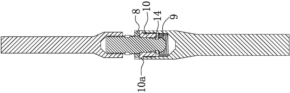
[0037] The structure and working principle of this embodiment are basically the same as that of Embodiment 1, the difference is that, as Figure 4 and Figure 5 As shown, the end of the insertion rod 5 has a step-shaped clamping platform 9, and the clamping mechanism 7 includes a spring assembly 14 screwed to the lower connection chamber 4. When the insertion rod 5 is inserted into the spring assembly 14 At this time, rotating the ring gear 6 can make the card table 9 close to the spring assembly 14 and make the card table 9 and the end of the spring assembly 14 form a snap fit. Since the structure of the shrapnel assembly 14 is relatively simple, it is easy to assemble and use.

[0038] combine Figure 7 As shown, the shrapnel assembly 14 includes a shrapnel threaded portion 15 that is threadedly engaged with the lower connection chamber 4 , and the end of the shrapnel threaded portion 15 is provided with a number of springs evenly distributed along the axial direction of t...


PUM


Abstract

The invention belongs to the technical field of building, and relates to an upper-screwing lower-locking automatic insertion rod adjustable connection component. The upper-screwing lower-locking automatic insertion rod adjustable connection component comprises an upper connection rod and a lower connection rod, wherein the end part of the upper connection rod is provided with an upper connection cavity, and the end part of the lower connection rod is provided with a lower connection cavity; the upper connection cavity and the lower connection cavity are separately internally provided with inner threads; the upper connection rod is internally connected with a connection rod through threads; the lower connection rod is internally connected with a clamping mechanism through threads; the outer wall of the insertion rod is provided with a tooth ring which is integrally moulded with the insertion rod; when the insertion rod is inserted into the clamping mechanism, the position of the end part of the insertion rod in the clamping mechanism can be adjusted by rotating the tooth ring, so that the insertion rod is in clamping match with the clamping mechanism; and a gear ring is connected with the insertion rod through threads, and the gear ring can approach the lower connection rod and be tightly pressed against the end part of the lower connection rod by rotating the gear ring. By adopting the upper-screwing lower-locking automatic insertion rod adjustable connection component, connection can be conveniently performed through mechanical operation; and the connection distance is adjustable, so that dual effects of uplifting resistance and pressing resistance can be achieved, and connection is firm and reliable.

Description

technical field [0001] The invention belongs to the technical field of construction, and relates to an adjustable screw-up and lock-down automatic insertion rod-adjustable connector, which is suitable for quick connection between objects. Background technique [0002] Connectors are usually used for the connection between two objects, especially in recent years, because of their convenience and speed, they have been developed rapidly. However, the existing connectors have certain limitations because the distance between them cannot be adjusted. For this reason, the applicant has previously applied for an adjustable distance connector [Application No.: 201410042392.8], which includes two connectors, one of which is provided with a plug connector, and the other connector is provided with a An adjusting bolt assembly capable of adjusting the length, the plug joint can be inserted into the adjusting bolt assembly, when the adjusting bolt assembly adjusts the length, the plug joi...

Claims


Application Information

Patent Timeline
Patent Type & Authority Applications(China)
IPC IPC(8): F16B7/04F16B7/18E02D5/52E04B1/18E04B1/58
CPCE02D5/526E02D2600/20E04B1/185E04B1/585F16B7/042F16B7/182F16B7/187
Inventor 周兆弟
Owner 周兆弟
Why Eureka
Try Eureka