
Signal processing device

A signal processing device and signal technology, applied in measurement devices, radio wave reflection/re-radiation, utilization of re-radiation, etc., can solve problems such as false detection, improve sensitivity, reduce the possibility of false detection, and prevent false detection. less likely effect

Inactive Publication Date: 2016-07-20
PANASONIC INTELLECTUAL PROPERTY MANAGEMENT CO LTD
View PDF7 Cites 5 Cited by
  • Summary
  • Abstract
  • Description
  • Claims
  • Application Information

AI Technical Summary

Problems solved by technology

However, when the object detection device 101 is used outdoors, for example, due to the movement of objects other than the detection target (detection target object), there is a possibility that an object other than the detection target (detection target object) is erroneously detected as the detection target object. detection

Method used


Image

  • Signal processing device
  • Signal processing device
  • Signal processing device

Examples


Embodiment Construction

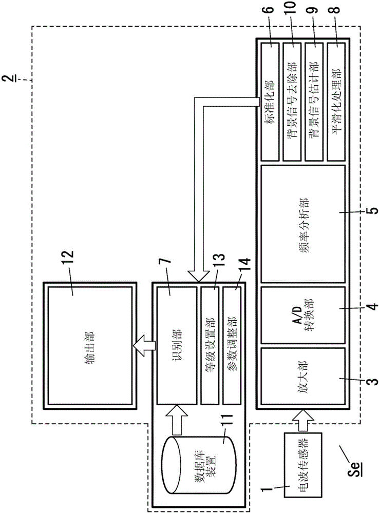
[0054] The following reference Figure 1 to Figure 35 The signal processing device of this embodiment will be described.

[0055] The signal processing device 2 is configured to perform signal processing on the sensor signal output from the radio wave sensor 1 . Notice, figure 1 It is a block diagram showing a sensor device Se including a radio wave sensor 1 and a signal processing device 2 .

[0056] The radio wave sensor 1 may be a Doppler sensor. The Doppler sensor sends electric waves of a predetermined frequency to the detection area and receives electric waves reflected by objects moving in the detection area, and outputs the difference between the frequency of the transmitted electric waves and the frequency of the received electric waves The corresponding Doppler frequency of the sensor signal. Thus, the sensor signal is an analog time axis signal corresponding to the motion of the object.

[0057] The radio wave sensor 1 includes: a transmitter for sending radio...


PUM


Abstract

Provided is a signal processing device that can reduce erroneous detections stemming from movements of an object other than a detection subject. The signal processing device (2) performs signal processing of a sensor signal from a radio sensor (1). A parameter adjustment unit (14) alters parameters that adjust the detection sensitivity of objects during a recognition process. Also, on the basis of a sensitivity level set by a level setting unit (13), the parameter adjustment unit (14) sets parameters in a manner such that the object detection sensitivity becomes higher when the sensitivity level is high and sets parameters in a manner such that the object detection sensitivity becomes lower when the sensitivity level is low.

Description

technical field [0001] The present invention relates generally to signal processing devices, and more particularly to signal processing devices for signal processing sensor signals from sensors for receiving wireless signals reflected by objects. Background technique [0002] Traditionally, the proposed Figure 36 An illumination system of the structure shown (see Japanese Patent Laid-Open No. 2011-47779, hereinafter referred to as "Document 1"). The lighting system includes: an object detection device 101, which includes a sensor 110, wherein the sensor 110 is configured to detect the presence or absence of a detection target object in a detection area and output a sensor signal; The device 101 controls the lighting state of the lighting fixture 102 . [0003] The sensor 110 is a millimeter wave sensor, wherein the millimeter wave sensor is configured to transmit a millimeter wave to a detection area and receive a millimeter wave reflected by a detection target object movi...

Claims


Application Information

Patent Timeline
Patent Type & Authority Applications(China)
IPC IPC(8): G01S13/56G01V3/12
CPCG01S7/2922G01S7/2927G01S7/354G01S13/56G01S13/88
Inventor 增田达男
Owner PANASONIC INTELLECTUAL PROPERTY MANAGEMENT CO LTD
Learn More