Electric cabinet device control system

A device control and electrical cabinet technology, applied in the field of electrical cabinets, can solve the problems of difficult control of pivot angle, manual operation, and difficult operation, and achieve the effect of compact structure, convenient use and reliable operation

Inactive Publication Date: 2016-07-20
王启先
View PDF3 Cites 2 Cited by
  • Summary
  • Abstract
  • Description
  • Claims
  • Application Information

AI Technical Summary

Problems solved by technology

Usually, such a carrier is difficult to operate manually due to its heavy weight, and it is easy to cause impacts such as collisions on the components in it, thus causing potential safety hazards
And its pivot angle is also difficult to control, which brings difficulties to the operation

Method used


Image

  • Electric cabinet device control system
  • Electric cabinet device control system
  • Electric cabinet device control system

Examples


Embodiment Construction

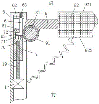
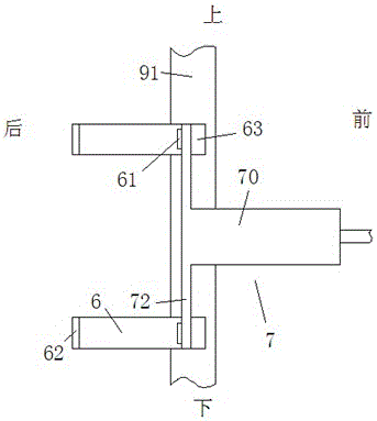
[0012] Combine below Figure 1-3 The present invention will be described in detail.

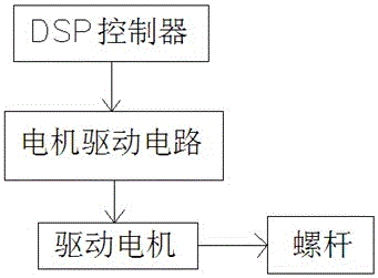
[0013] According to an embodiment of an electrical cabinet device control system, it includes a fixed frame part 8 and a functional device carrier 9 that is pivotable relative to the fixed frame part 8, and the functional device carrier 9 is loaded with an operating side 921 and the functional device device 92 on the wiring side 922, the end of the functional device carrier 9 close to the fixed frame part 8 is fixedly arranged with the hinge shaft 81 fixedly arranged near the rear end of the fixed frame part 8. A pivoting drive gear sleeve 91 that is rotatably matched, the fixed frame part 8 is provided with a rack assembly that can move in the forward and backward direction driven by the screw rod 19 extending in the forward and backward direction driven by the drive motor 1, and the DSP control The device is electrically connected to the drive motor 1 in the electrical cabinet device throu...


PUM


Abstract

The invention relates to an electric cabinet device control system. The control system comprises a digital signal processor (DSP) controller, a motor driving circuit and an electric cabinet device, wherein the electric cabinet device comprises a fixed rack part (8) and a functional device bearing rack (9), wherein the functional device bearing rack (9) can pivot relative to the fixed rack part (8), a functional device (92) is carried on the functional device bearing rack (9) and is provided with an operating side (921) and a wiring side (922), a pivot driving gear sleeve (91) is fixedly arranged at end part, close to the fixed rack part (8), of the functional device bearing rack (9) and is rotatably matched with a hinge shaft (81), the hinge shaft (81) is fixedly arranged at a position near to the rear end part of the fixed rack part (8), a rack assembly is arranged in the fixed rack part (8) and can move forwards and backwards by the driving of a screw rod (19), and the screw rod (19) is driven to rotate by a driving motor (1) and extends forwards and backwards.

Description

technical field [0001] The invention relates to the field of electric cabinets, in particular to an electric cabinet device control system. Background technique [0002] Various functional devices are provided in the electrical cabinet to complete corresponding functions, such as various circuit boards or other electrical components. Typically, these devices are placed on a carrier for easy wiring and maintenance. [0003] In order to facilitate maintenance operations, there is a pivotable circuit board carrier, which can be pivoted open to perform operations such as replacing electrical components. Usually, such a carrier is difficult to operate manually due to reasons such as its heavy weight and is likely to cause impacts such as collisions on components therein, thus causing potential safety hazards. And its pivot angle is also difficult to control, which brings difficulties to the operation. Contents of the invention [0004] The object of the present invention is ...

Claims


Application Information

Patent Timeline
Patent Type & Authority Applications(China)
IPC IPC(8): H05K7/14
CPCH05K7/1402H05K7/1414
Inventor 王启先
Owner 王启先
Why Eureka
Try Eureka