Eureka AIR delivers breakthrough ideas for toughest innovation challenges, trusted by R&D personnel around the world.

Method for computing lens distortion of photographing module

A technology of lens distortion and computational photography, applied in computing, image enhancement, image communication, etc., can solve the problems of large amount of calculation and long shooting time.

Inactive Publication Date: 2016-07-20
NINGBO SUNNY OPOTECH CO LTD
View PDF12 Cites 6 Cited by
  • Summary
  • Abstract
  • Description
  • Claims
  • Application Information

AI Technical Summary

Problems solved by technology

However, this method is time-consuming and computationally intensive

Method used

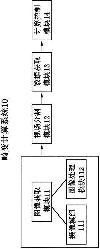
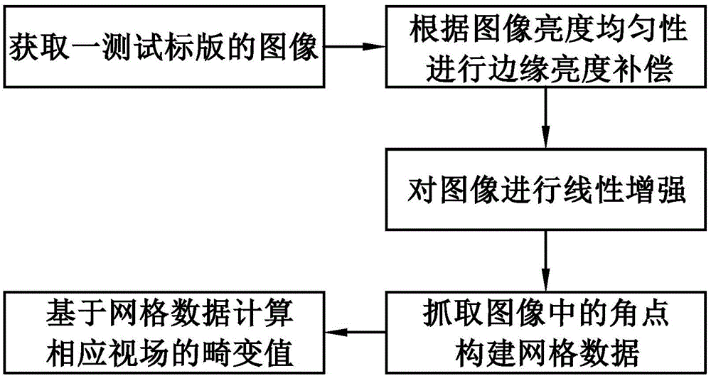

Image

  • Method for computing lens distortion of photographing module
  • Method for computing lens distortion of photographing module
  • Method for computing lens distortion of photographing module

Examples


Embodiment Construction

[0027] The following description serves to disclose the present invention to enable those skilled in the art to carry out the present invention. The preferred embodiments described below are only examples, and those skilled in the art can devise other obvious variations. The basic principles of the present invention defined in the following description can be applied to other embodiments, variations, improvements, equivalents and other technical solutions without departing from the spirit and scope of the present invention.

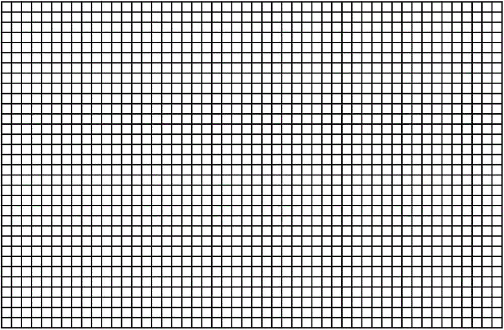
[0028] The method for calculating the lens distortion of the camera module provided by the present invention first needs to provide a test standard plate, and a grid is drawn on the test standard plate, such as figure 1 As shown, the grid is composed of at least two horizontal straight line segments parallel to each other and at least two vertical straight line segments perpendicular to each of the horizontal straight line segments. Each horizontal strai...


PUM


Abstract

The invention discloses a method for computing lens distortion of a photographing module. The method comprises following steps of (a), utilizing the photographing module to obtain a test chart image; (b), capturing angular points in the image; forming grid data; and (c), computing the lens distortion value of the photographing module based on the grid data.

Description

technical field [0001] The invention relates to a method for calculating lens distortion of a camera module. Background technique [0002] Lens distortion is a general term for the inherent perspective distortion of optical lenses, but this distortion is an inherent characteristic of the lens, so it cannot be eliminated, but can only be improved. To improve the distortion, you need to know the degree of distortion, that is, calculate the distortion. [0003] The traditional distortion calculation method first needs to take pictures of the standard plate, then manually locate the corresponding points in the field of view from the pictures taken, and finally calculate the distortion value of the field of view according to the position of each point. However, this method is time-consuming and computationally intensive. Contents of the invention [0004] An object of the present invention is to provide a method for calculating the lens distortion of a camera module, which can...

Claims


Application Information

Patent Timeline
Patent Type & Authority Applications(China)
IPC IPC(8): H04N5/232G06T5/00
Inventor 张扣文郑杰
Owner NINGBO SUNNY OPOTECH CO LTD
Why Eureka
Eureka Blog
Learn More