Glue detection method and device

A glue testing and gluing technology, applied in the direction of optical testing flaws/defects, etc., can solve problems such as poor efficiency of hot melt adhesives, and achieve the effect of improving efficiency and reducing wastage time.

Active Publication Date: 2019-04-12
威光自动化设备(厦门)有限公司
View PDF7 Cites 0 Cited by
  • Summary
  • Abstract
  • Description
  • Claims
  • Application Information

AI Technical Summary

Problems solved by technology

[0008] In view of this, the object of the present invention is to improve the inefficiency of traditional detection of hot melt adhesive coated on the substrate

Method used


Image

  • Glue detection method and device
  • Glue detection method and device
  • Glue detection method and device

Examples


Embodiment Construction

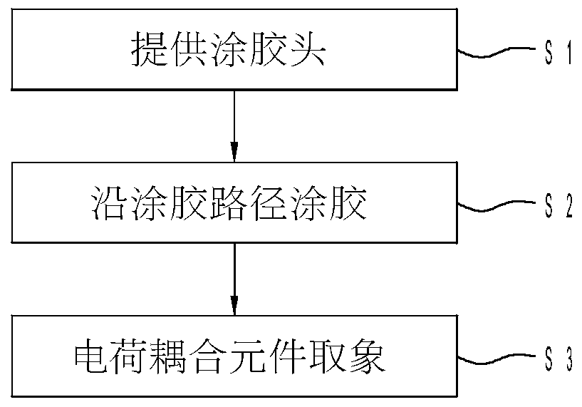
[0028] see figure 1 , illustrating the glue detection method provided by the present invention, including implementing the following steps S1 to S3:

[0029] Step S1: providing a glue applicator.

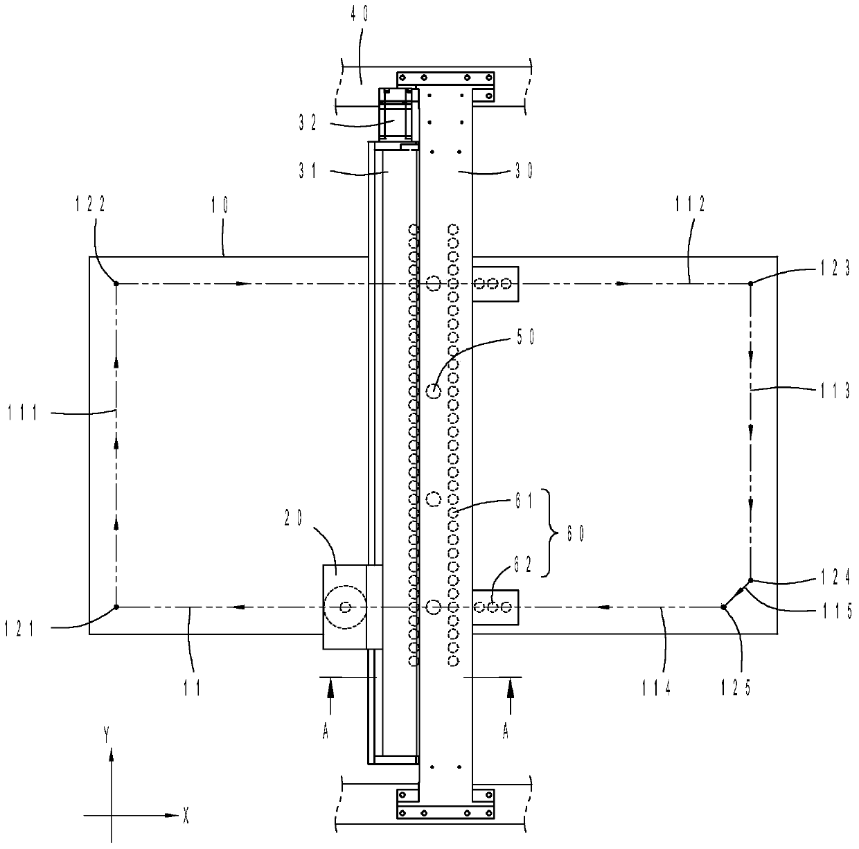
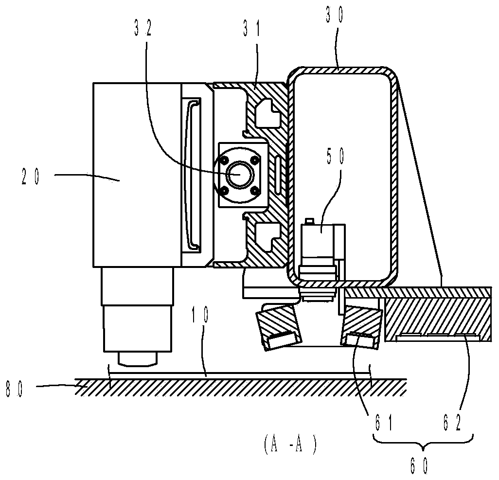
[0030] implementation, such as figure 2 As shown, the present invention provides a glue applicator 20 with biaxial movement capability. The above-mentioned biaxial refers to the X axis and the Y axis in practice. The X-axis and the Y-axis move, so that the hot melt adhesive contained in the glue head 20 is coated on the object (such as a substrate).

[0031] Step S2: apply glue along the glue application path.

[0032] implementation, such as figure 2 As shown, it is illustrated that the substrate 10 is moved to the bottom of the gluing head 20 through a carrier (such as a chain, a belt, or a roller, etc.). The glue path 11 is coated with hot melt glue on the substrate 10. The glue path 11 is formed around a quadrilateral track in practice, and the quadrilateral track is loca...


PUM


Abstract

The invention provides a gluing detection method, comprising providing a gluing head with a biaxial movement function, performing gluing along a gluing path on a substrate, and sampling images on the gluing path through a charge coupled element moving with the gluing head, wherein the charge coupled element moves with at least one of the two axes of the gluing head. The invention further provides a gluing detection device using the method. Accordingly, the problem of low efficiency of gluing hot melt glue on the substrate in traditional detection can be solved.

Description

technical field [0001] The invention relates to a hot-melt glue coating technology, in particular to a glue coating detection method and a device thereof. Background technique [0002] As we all know, a solar panel is to sandwich several solar cells between two substrates, and connect conductive lines between the cells to the hub of the glass frame, so as to conduct the electric energy collected and converted by the solar cells. Among them, in order to prevent liquid (such as water) from infiltrating between the two substrates, before the two substrates are bonded, hot melt adhesive is applied to the surrounding frames of the two substrates, so that the liquid can be prevented after the two substrates are bonded. Penetration, thereby improving the durable service life of solar panels. [0003] At present, the application of hot melt adhesive on the substrate is mostly carried out by automatic glue applicators, and the automatic glue applicator must be able to effectively co...

Claims


Application Information

Patent Timeline
Patent Type & Authority Patents(China)
IPC IPC(8): G01N21/89
Inventor 黄金福郑香弘
Owner 威光自动化设备(厦门)有限公司
Why Eureka
Try Eureka