Unbalance ridding mechanism for cross-flow fan dynamic balance emendation

A cross-flow fan blade and deduplication technology, which is used in static/dynamic balance testing, machine/structural component testing, measuring devices, etc. The effect of high pass rate

Active Publication Date: 2016-07-20
GUANGDONG SUNWILL PRECISING PLASITC CO LTD
View PDF6 Cites 7 Cited by
  • Summary
  • Abstract
  • Description
  • Claims
  • Application Information

AI Technical Summary

Problems solved by technology

The structure has poor angular accuracy and low efficiency

Method used


Image

  • Unbalance ridding mechanism for cross-flow fan dynamic balance emendation
  • Unbalance ridding mechanism for cross-flow fan dynamic balance emendation
  • Unbalance ridding mechanism for cross-flow fan dynamic balance emendation

Examples


no. 1 example

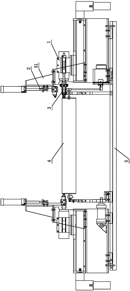
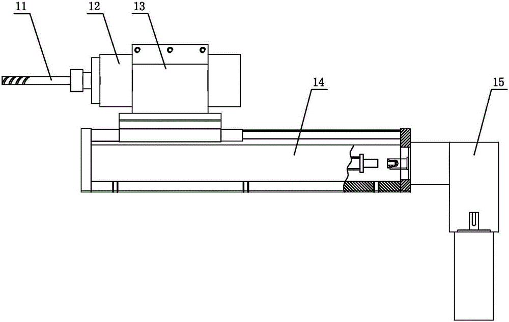
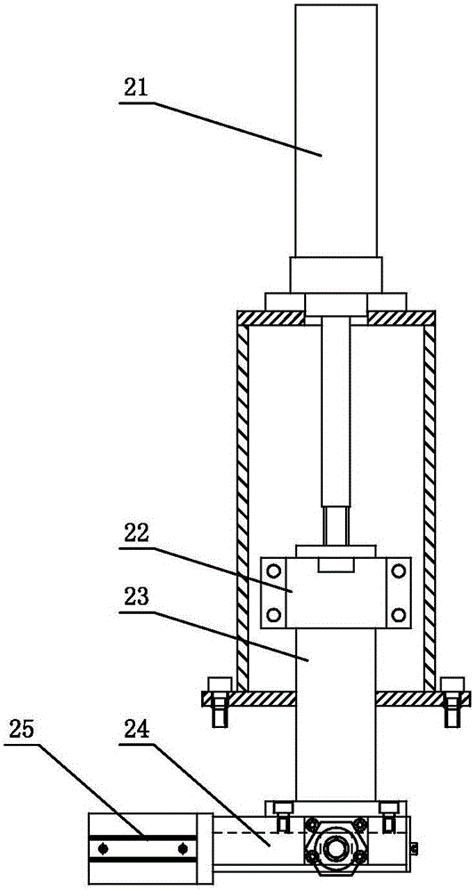
[0027] see Figure 1-Figure 6 , the weight removal mechanism used for the dynamic balance correction of cross-flow fan blades, including a base 5, the cross-flow fan blades 4 are clamped on the base 5, and the base 5 is provided with drilling and reorganization for drilling weight removal Part 1, an end face tightening assembly 2 for counteracting the drilling force, and a debris absorption assembly 3 for removing debris; Two sets are respectively placed at both ends of the cross-flow fan 4. Specifically, the drilling and weight removal component 1, the end face tightening component 2 and the debris absorption component 3 are symmetrically distributed on the cross-flow fan 4 along the central section of the cross-flow fan 4. Both ends; the end surface tightening mechanism 2 is independently installed on the small gantry frame 51 of the base 5 . When the drilling and milling cutter 11 on the drilling and removing weight component 1 is drilling, the end face tightening componen...

no. 2 example

[0036] see Figure 7 , this weight-removing mechanism for cross-flow fan blade dynamic balance correction is different from the first embodiment in that: the debris absorption assembly 3 includes a drilling sleeve 31, a drilling sleeve bracket 32 ​​and a sliding guide rod 33, The drilling sleeve 31 is fixedly connected to the drilling sleeve bracket 32, and two sliding guide rods 33 are arranged and distributed on both sides of the symmetry. On the motor base 13 of the drilling weight removal assembly 1, a spring 34 is sleeved on the sliding guide rod 33, and the two ends of the spring 34 act on the drilling sleeve bracket 32 ​​and the guide rod seat 37 respectively, and the sliding guide rod 33 A locking block 36 is assembled through the end of the drilling sleeve support 32 to adjust the movement range of the drilling sleeve 31 , thereby adjusting the drilling depth.

[0037] Other parts not described are the same as those of the first embodiment, and will not be analyzed a...


PUM


Abstract

The invention discloses an unbalance ridding mechanism for cross-flow fan dynamic balance emendation, which comprises a base. A cross-flow fan is clamped on the base; the base is provided with two sets of drilling unbalance ridding assemblies for drilling unbalance ridding and two sets of end surface top tight assemblies for cancelling the drilling force; the two sets of the drilling unbalance ridding assemblies and / or the two sets of the end surface top tight assemblies are respectively arranged at two ends of the cross-flow fan; and when a drilling milling cutter on the drilling unbalance ridding assembly performs drilling processing, the end surface top tight assemblies at the same side do not act on the cross-flow fan, and the end surface top tight assemblies at the opposite side act on the cross-flow fan to cancel the drilling force. Two sets of the drilling unbalance ridding assemblies and the two sets of the end surface top tight assemblies are arranged symmetrically, a uniform stress layout with drilling unbalance ridding at one end and top tight at the other end is adopted, axial offset of the cross-flow fan caused by the drilling force can be effectively avoided, the precision of an unbalance test system is ensured on one hand, and on the other hand, the drilling depth precision can be ensured; and in addition, as a debris absorption assembly is arranged, debris generated by drilling can be timely cleaned, and cleanness of the working environment can be effectively ensured.

Description

technical field [0001] The invention relates to a device for dynamic balance of cross-flow fan blades, in particular to a weight-removing mechanism for dynamic balance correction of cross-flow fan blades. Background technique [0002] As the demand for air conditioners continues to increase, the production efficiency of cross-flow fan blades, which are key structural components in air conditioners, is an unavoidable problem for manufacturers. In the manufacturing process of cross-flow fan blades, the measurement and calibration process of its dynamic balance is essential. If the unbalanced products are not up to the standard, if they are used in the production of air conditioners, they will cause problems such as loud noise and serious wear of the rotating shaft. At present, the more common cross-flow wind blade dynamic balance correction work is done manually, which has problems such as low efficiency, high labor cost, and uneven pass rate. [0003] Chinese Patent Documen...

Claims


Application Information

Patent Timeline
Patent Type & Authority Applications(China)
IPC IPC(8): G01M1/34
CPCG01M1/34
Inventor 黄禹龙仕均丁斌龚时华陈志
Owner GUANGDONG SUNWILL PRECISING PLASITC CO LTD
Why Eureka
Try Eureka