
Stirring and heating type drum drying system

A stirring heating and drum drying technology, applied in non-progressive dryers, heating devices, drying solid materials, etc., can solve problems such as unfavorable energy saving, consumption reduction and emission reduction, poor drying effect, and difficulty in timely discharge of heat transfer oil. , to achieve the effect of simple structure, less investment and improved heat exchange efficiency

Inactive Publication Date: 2016-07-20
CHONGQING SUTEXIN ELECTRONICS CO LTD
View PDF0 Cites 1 Cited by
  • Summary
  • Abstract
  • Description
  • Claims
  • Application Information

AI Technical Summary

Problems solved by technology

Although the heat-conducting oil-type drum drying device can meet the use requirements to a certain extent, it is difficult to discharge the low-temperature heat-conducting oil trapped between the outer cylinder and the inner cylinder in time, resulting in the temperature between the outer cylinder and the inner cylinder Uneven, the drying effect is not good, which is not conducive to energy saving and emission reduction

Method used


Image

  • Stirring and heating type drum drying system
  • Stirring and heating type drum drying system
  • Stirring and heating type drum drying system

Examples


Embodiment Construction

[0024] The present invention will be further described below in conjunction with the accompanying drawings and specific embodiments, so that those skilled in the art can better understand the present invention and implement it, but the examples given are not intended to limit the present invention.

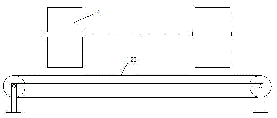
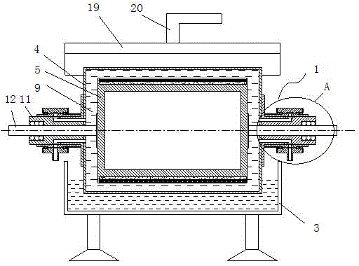
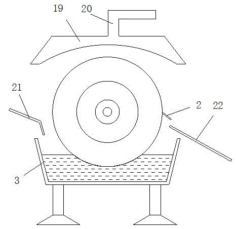
[0025] like figure 1 Shown is a schematic structural view of an embodiment of the stirring and heating drum drying system of the present invention. The stirring and heating drum drying system of this embodiment includes a material conveying device 23 and at least one stirring and heating drum dryer arranged along the material conveying device 23. The stirring and heating drum dryer of this embodiment includes a drying drum 1, The scraper 2 and the feed liquid tray 3, the drying drum 1 includes an outer cylinder 4, and the outer cylinder 4 is provided with an inner cylinder 5 coaxial with its rotation and coaxially, and the outer peripheral wall of the inner cylinder 5 is provided ...


PUM


Abstract

The invention discloses a stirring and heating type drum drying system. The stirring and heating type drum drying system comprises a material conveying device and at least one stirring and heating type drum drying machine arranged along the material conveying device. Each stirring and heating type drum drying machine comprises a drying drum, a scraping knife and a liquid material disc. The drying drum comprises an outer drum body. An inner drum body which is rotationally matched with the outer drum body and is coaxial with the outer drum body is arranged in the outer drum body. A heat insulation layer, an electrical heating layer and a thin wall heat conduction layer are sequentially arranged on the peripheral wall of the inner drum body from inside to outside. A medium cavity for storing a heat conduction medium is arranged between the outer drum body and the inner drum body. A stirring structure for stirring the heat conduction medium is evenly and annularly distributed on the peripheral wall of the thin wall heat conduction layer and comprises stirring teeth arranged on the peripheral wall of the thin wall heat conduction layer in an array manner. The bottom of the outer drum body is located in the liquid material disc. A knife edge of the scraping knife is tightly attached to the outer surface of the outer drum body. A material receiving plate communicating with the material conveying device is arranged below the scraping knife. The stirring and heating type drum drying system has the beneficial effects that heat conduction efficiency is high, and heating is uniform.

Description

technical field [0001] The invention belongs to the technical field of drying equipment, and in particular relates to a stirring and heating drum drying system. Background technique [0002] The drum drying device is a normal-pressure drying equipment that heats the liquid material or slurry attached to the outer wall of the cylinder by heat conduction to vaporize the water. When the drum rotates slowly, the material adheres to the outer surface of the drum in the form of a film, the water is vaporized and scattered in the surrounding air, and the dry material attached to the outer wall is scraped off by the scraper in the form of flakes and falls into the discharge port. Because the heat transfer method of the drum drying device is from the inside to the outside, it has the advantages of uniform material distribution, thin material layer, large temperature gradient and high heat utilization rate, and is widely used in chemical production. [0003] The existing drum heating...

Claims


Application Information

Patent Timeline
Patent Type & Authority Applications(China)
IPC IPC(8): F26B11/06F26B23/10F26B25/00
Inventor 席锡峰
Owner CHONGQING SUTEXIN ELECTRONICS CO LTD
Learn More