
Orientated locating type electromagnetic jaw clutch device

An electromagnetic clutch, directional positioning technology, applied in magnetic drive clutches, clutches, non-mechanical drive clutches, etc., can solve the problems of poor positioning and transmission system movement, and achieve the effects of good positioning, large transmission torque and simple structure

Inactive Publication Date: 2016-07-20
TIANJIN BAIDE SIFANG TRANSMISSION EQUIP
View PDF0 Cites 3 Cited by
  • Summary
  • Abstract
  • Description
  • Claims
  • Application Information

AI Technical Summary

Problems solved by technology

[0004] Most of the existing clutches are single-disc friction structures with poor positioning, while the existing jaw clutches can transmit torque in both forward and reverse directions, which may easily cause movement of the transmission system

Method used


Image

  • Orientated locating type electromagnetic jaw clutch device

Examples


Embodiment Construction

[0021] The present invention will be further described below with reference to the accompanying drawings and examples, and the embodiments of the present invention include but not limited to the following examples.

[0022] Embodiment: In order to achieve the above object, the technical scheme adopted in the present invention is as follows:

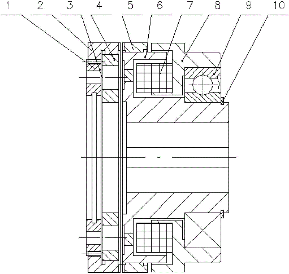
[0023] Such as figure 1 As shown, the present invention provides a directional positioning jaw type electromagnetic clutch device, including a coupling plate 1, an armature ring 2, a return spring 3, an armature 4, a baffle ring 5, a baffle 6, a coil 7, and a yoke 8. The bearing 9 and the bearing ring 10, the coil 7 are installed in the slot of the yoke 8, the armature ring 2 and the return spring piece 3 are respectively installed on the connecting plate 1, and the connecting plate 1 is connected with the driven shaft through its inner hole, The inner teeth of the armature gear ring 2 can slide on the outer teeth of the connecting plate...


PUM


Abstract

The invention discloses an orientated locating type electromagnetic jaw clutch device. The orientated locating type electromagnetic jaw clutch device comprises a connection plate, an armature gear ring, a reset spring leaf, an armature, a baffle gear ring, a baffle, coils, a magnetic yoke, a bearing and a bearing check ring, wherein the coils are installed in a magnetic yoke groove, the armature gear ring and the reset spring leaf are installed on the connection plate, and the connection plate is connected to a driven shaft through an inner hole of the connection plate; internal teeth of the armature gear ring can slide on external teeth of the connection plate, and the end face of the armature gear ring is provided with trapezoidal teeth capable of being meshed with trapezoidal teeth of the baffle gear ring; the armature is installed on the armature gear ring and is connected to the reset spring leaf; when the coils are energized, the armature can be attracted, the reset spring leaf can be deformed due to pulling, and the trapezoidal teeth of the armature gear ring can be meshed with the trapezoidal teeth of the baffle gear ring; when the power of the coils is cut off, the armature can be released and pulled to the original position, the reset spring leaf can be reset, and the trapezoidal teeth of the armature gear ring can be separated from the trapezoidal teeth of the baffle gear ring.

Description

technical field [0001] The invention belongs to the field of transmission machinery, in particular to a directional positioning jaw type electromagnetic clutch device. Background technique [0002] Generally, in a car, the clutch is located in the flywheel housing between the engine and the gearbox, and the clutch assembly is fixed on the rear plane of the flywheel with screws, and the output shaft of the clutch is the input shaft of the transmission. During the driving process of the car, the driver can step on or release the clutch pedal as needed to temporarily separate the engine from the gearbox and gradually engage it, so as to cut off or transmit the power input from the engine to the gearbox. [0003] Clutches are common components in mechanical transmissions that can disengage or engage the transmission system at any time. The basic requirements are: smooth joint, rapid and thorough separation; convenient adjustment and repair; small external size; small mass; good...

Claims


Application Information

Patent Timeline
Patent Type & Authority Applications(China)
IPC IPC(8): F16D27/09F16D27/14
CPCF16D27/09F16D27/14
Inventor 荣斌
Owner TIANJIN BAIDE SIFANG TRANSMISSION EQUIP
Learn More