
Fire extinguish wall

A fire extinguishing wall and fire extinguishing material technology, applied in the field of disaster prevention and mitigation of building structures, can solve problems such as large secondary water damage in non-fire areas, need to replace, electric shock casualties, etc., to ensure property safety, fast response, and fire extinguishing effect Good results

Inactive Publication Date: 2016-07-20
JIANGSU EFFORT TECH & DEV
View PDF0 Cites 3 Cited by
  • Summary
  • Abstract
  • Description
  • Claims
  • Application Information

AI Technical Summary

Problems solved by technology

[0002] With the rapid development of the domestic economy, more and more tall and large spaces appear in contemporary buildings. In order to maintain a spacious and transparent effect and meet the requirements of use, such spaces have broken through the regulations on the maximum allowable area of ​​​​the fire compartment, but The requirements for fire extinguishing facilities have also been increased accordingly.
In the event of a fire, the four walls of the room have a large fire area and are an important structure that can effectively block the spread of fire. At present, most of the fire-fighting methods at home and abroad are to set up additional fire-fighting facilities, and the use of the building itself has not been considered. The effective space for active fire extinguishing, this kind of passive fire extinguishing device increases the additional cost, and needs to be replaced after one use, and the fire extinguishing effect is not ideal at the same time
In addition, water spraying systems are mostly used at home and abroad at present, and water spraying systems are likely to cause large secondary water damage losses and electric shock casualties to non-fire areas

Method used


Image

  • Fire extinguish wall
  • Fire extinguish wall
  • Fire extinguish wall

Examples


Embodiment Construction

[0014] The present invention will be described in further detail below in conjunction with the accompanying drawings.

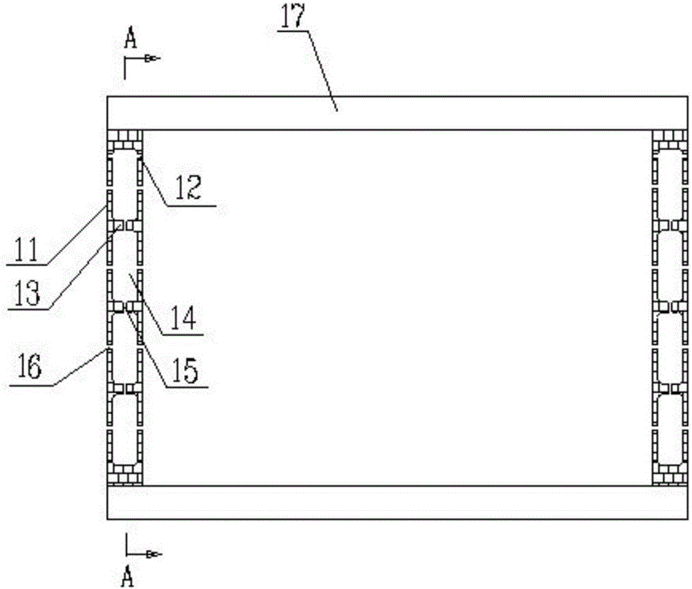
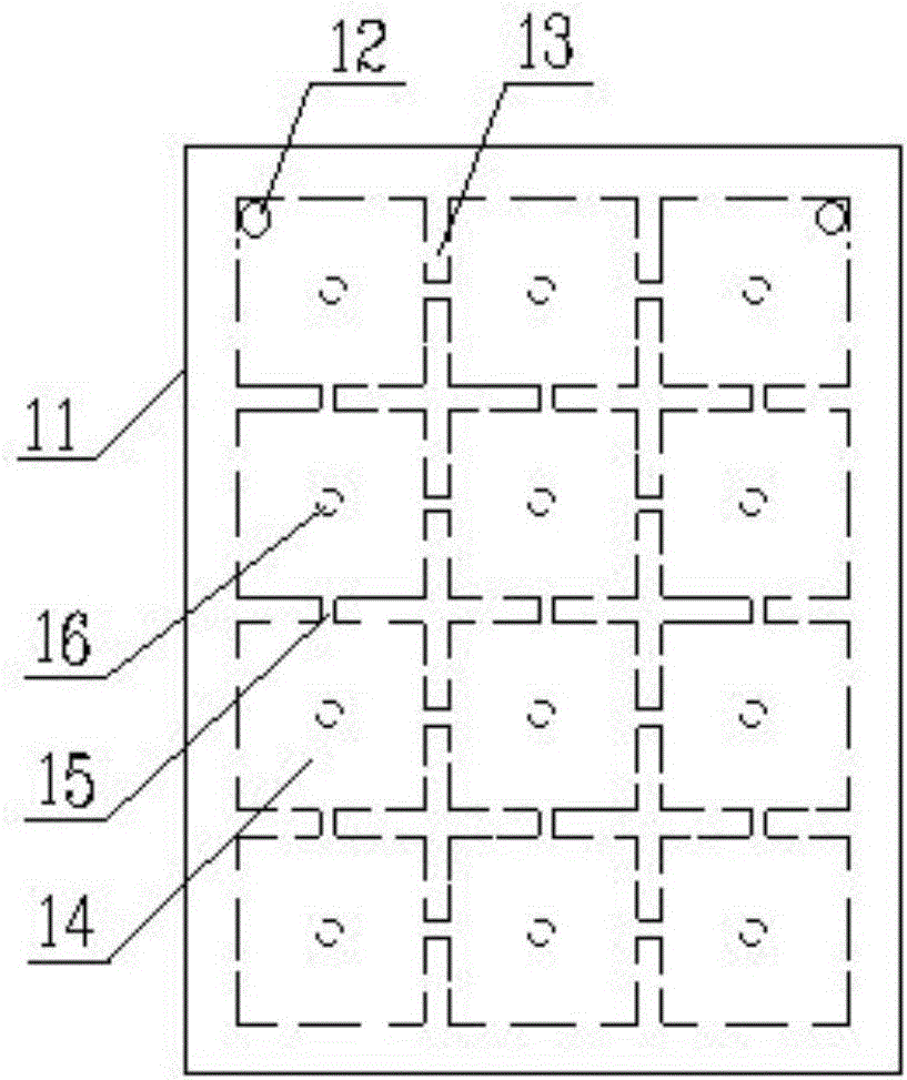
[0015] Such as Figure 1 to Figure 4 The shown fire extinguishing wall includes a wall 11, the wall 11 is arranged between two floor slabs 17, a plurality of cavities 14 are arranged in the wall 11, column gratings 13 are arranged between the cavities 14, and through The feeding channels 15 are connected to each other, each cavity 14 is equipped with fire extinguishing materials, the upper part of the wall 11 is provided with a feeding port 12, and the two sides of the wall 11 are provided with discharge ports 16; the fire extinguishing control system is installed on the wall 11 The fire extinguishing control system includes a processor, a fire extinguishing alarm device, and a plurality of smoke sensors and temperature sensors distributed on both sides of the wall 11. The smoke sensor, temperature sensor and fire extinguishing alarm device are connected to t...


PUM


Abstract

The invention discloses a fire extinguish wall. A plurality of cavities (14) are formed in a wall body (11). Columnsyns (13) are arranged between the cavities (14), and the cavities (14) communicate with one other through charging channels (15). A fire extinguish material is loaded in each cavity (14). Material feed openings (12) are formed in the upper portion of the wall body (11). Material discharging openings (16) are distributed in the two sides of the wall body (11). A fire extinguish control system installed on the wall body (11) comprises a processor, fire extinguish alarming devices, a plurality of smoke sensors and temperature sensors, and the smoke sensors and the temperature sensors are distributed on the two sides of the wall body (11). The smoke sensors, the temperature sensors and the fire extinguish alarming devices are connected with the processor, and the fire extinguish alarming devices are arranged on the material discharging openings (16). Fire protection and fire extinguish devices are arranged in the space of the four walls of a room, the wall spaces are fully used for achieving proactive fire protection and fire extinguish, and the walls can be repeatedly used, so that the cost is reduced. The four walls respond simultaneously, the fire extinguish effect is good, secondary waterlogging loss is avoided, and safety is ensured.

Description

technical field [0001] The invention relates to a fire extinguishing device, in particular to a fire extinguishing wall, which belongs to the field of disaster prevention and mitigation of building structures. Background technique [0002] With the rapid development of the domestic economy, more and more tall spaces appear in contemporary buildings. In order to maintain a spacious and transparent effect and meet the requirements of use, such spaces have broken through the regulations on the maximum allowable area of ​​​​the fire compartment, but The requirements for fire extinguishing facilities have also been increased accordingly. In the event of a fire, the four walls of the room have a large fire-receiving area and are an important structure that can effectively block the spread of fire. However, most fire-fighting methods at home and abroad are to set up additional fire-fighting facilities, and the use of the building itself has not been considered. The effective space...

Claims


Application Information

Patent Timeline
IPC IPC(8): E04B2/00A62C35/00A62C37/40
CPCE04B2/00A62C35/00A62C37/40
Inventor 渠文姗
Owner JIANGSU EFFORT TECH & DEV
Learn More