
Pillow structure of A-shaped glass bracket

An A-shaped, glass technology, applied to external frames, containers to prevent mechanical damage, packaging of vulnerable items, etc., can solve the problems of slipping and breaking, and the lower part of the glass cannot be fixed by the slot, so as to ensure the beauty and prevent wear and tear. Effect

Inactive Publication Date: 2016-07-20
WUXI CITY NEW DISTRICT WEICHUANGLI MOLD FACTORY
View PDF0 Cites 2 Cited by
  • Summary
  • Abstract
  • Description
  • Claims
  • Application Information

AI Technical Summary

Problems solved by technology

[0002] The existing A-shaped glass support includes a bottom frame and an A-shaped support fixed on the upper part of the bottom frame, which are located on both sides of the bottom of the A-shaped support. The bottom frame is provided with a number of pillow bars arranged in parallel, and the pillow bars are provided with backing plates. There are card slots distributed along the length direction on the backing plate. When the glass is loaded, the lower part of the glass is clamped in the card slots to effectively prevent the glass from sliding. However, when the glass is loaded, it is inevitable to press the side between the adjacent card slots. Wall, because the material of the backing plate is relatively soft, the side wall is pressed to form a structure that bends and destroys the card slot, so that the lower part of the glass cannot be fixed by the card slot, and there is a risk of slipping and breaking

Method used


Image

  • Pillow structure of A-shaped glass bracket
  • Pillow structure of A-shaped glass bracket

Examples


Embodiment Construction

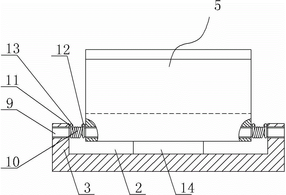
[0011] Such as Figure 1 to Figure 2 As shown, including the pillow bar 1, the upper middle position of the pillow bar 1 is provided with a U-shaped groove 2 arranged along the length direction, and a plurality of L-shaped clamping plates 5 are arranged in the U-shaped groove 2, and the L-shaped clamping plates 5 include an upper clamping plate 6 and the lower clamping plate 7 vertically fixed on the lower end of the upper clamping plate 6, the rotating shaft 9 runs through the connecting part 8 where the upper clamping plate 6 and the lower clamping plate 7 intersect and is supported on the two side walls 3 of the U-shaped groove 2, and is located on the L-shaped clamping plate. Between the connecting portion 8 of the plate 5 and the two side walls 3 of the U-shaped groove 2, a torsion spring 10 is sleeved on the rotating shaft 9, and the side walls at both ends of the connecting portion 8 and the side walls 3 of the U-shaped groove 2 are symmetrically arranged respectively. ...


PUM


Abstract

The invention provides a pillow structure of an A-shaped glass bracket. The pillow structure can effectively prevent the sidewalls between adjacent clamping grooves from being pressed by glass so that the glass can be effectively fixed and protected against slipping and breakage. The pillow structure comprises sleepers and is characterized in that U-shaped grooves are formed in the middles of the upper portions of the sleepers; a plurality of L-shaped clamping plates are arranged in the U-shaped grooves; each L-shaped clamping plate comprises an upper clamping plate and a lower clamping plate perpendicularly fixed to the lower end of the upper clamping plate; rotary shafts penetrate through the junctions where the upper clamping plates and the corresponding lower clamping plates intersect and are supported on the two sidewalls of the U-shaped grooves; the parts, located between the junctions and the two sidewalls of the U-shaped grooves, of the rotary shafts are sleeved with torsional springs; the two end sidewalls of the junctions and the sidewalls of the U-shaped grooves are symmetrically provided with stand columns correspondingly, and two spring legs of each torsional spring are connected to the corresponding stand columns correspondingly.

Description

technical field [0001] The invention relates to a glass transfer support, in particular to the structure of the pillow seat of the A-shaped glass support. Background technique [0002] The existing A-shaped glass support includes a bottom frame and an A-shaped support fixed on the upper part of the bottom frame, which are located on both sides of the bottom of the A-shaped support. The bottom frame is provided with a number of pillow bars arranged in parallel, and the pillow bars are provided with backing plates. There are card slots distributed along the length direction on the backing plate. When the glass is loaded, the lower part of the glass is clamped in the card slots to effectively prevent the glass from sliding. However, when the glass is loaded, it is inevitable to press the side between the adjacent card slots. Wall, because the material of the backing plate is relatively soft, the side wall forms a structure that bends and destroys the card slot after being press...

Claims


Application Information

Patent Timeline
Patent Type & Authority Applications(China)
IPC IPC(8): B65D85/48B65D61/00B65D81/05
Inventor 吕应军
Owner WUXI CITY NEW DISTRICT WEICHUANGLI MOLD FACTORY
Learn More