Low Power Harmonic Wake Up Radio

A harmonic and frequency technology, applied in the field of circuits that wake up the radio from low power mode, can solve the problems of current consumption and battery life

Active Publication Date: 2016-07-13
TEXAS INSTR INC
View PDF6 Cites 1 Cited by
  • Summary
  • Abstract
  • Description
  • Claims
  • Application Information

AI Technical Summary

Problems solved by technology

However, this approach requires more hardware built into the communication device
Another way to configure the radio of a communication device is to listen for incoming communications, which costs more current and battery life
Furthermore, with the increasing capabilities of modern communication devices, there is pressure to enable radio wake-up procedures to occur with low latency during extremely fast wake-up times while also conserving battery life

Method used


Image

  • Low Power Harmonic Wake Up Radio
  • Low Power Harmonic Wake Up Radio
  • Low Power Harmonic Wake Up Radio

Examples


Embodiment Construction

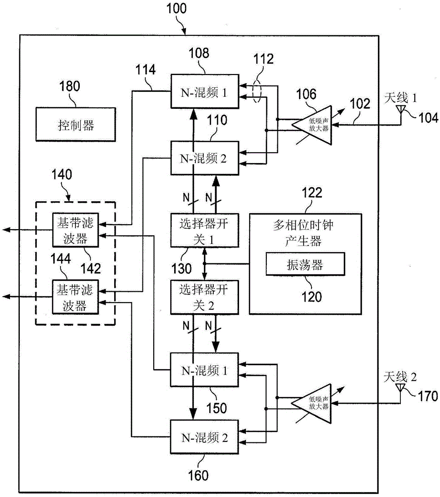
[0014] Referring now to the drawings and (specifically) figure 1 , an example apparatus 100 for converting radio frequency (RF) signals having multiple local oscillator phases will be described. Apparatus 100 includes an input 102 configured to receive RF signals. In the illustrated example, an input 102 is connected to receive signals from an antenna 104 that receives wireless signals. Typically, the input 102 runs to an amplifier, such as a low noise amplifier 106, to amplify the received signal. The output of amplifier 106 is provided to one or more receiver mixers 108 , 110 . Each receiver mixer 108, 110 includes at least one input 112 and output 114 configured to receive RF signals. Mixer 108 is configured to receive different phases of local oscillator 120 to enable passing different phases of the RF signal to output 114 . In one approach, the local oscillator 120 is part of a multi-phase clock generator or local oscillator network 122 configured to generate various ...


PUM


Abstract

The present invention relates to a low power harmonic wake up radio. A wireless receiver 100 includes a receiver mixer 108 having at least two sets (210,230,250) of switches (212,214,216,218)connected to selectively pass a portion of a received RF signal to the mixer's output. Different sets of the switches are activated by different phases of a local oscillator to effect passing of different phases of the RF signal to the output. These outputs are combined in various ways to obtain operation of the main receiver and the wake up receiver modes at harmonically related carrier frequencies with as low as possible subharmonic multi-phase clock generation network. This can be used to detect a wake up signal with a very fast response time, minimal area overhead, minimal power usage, and equal loading to the local oscillator network providing the phases to the mixer to maintain excellent phase balance and precise harmonic selectivity.

Description

technical field [0001] This disclosure relates generally to radios, and more particularly to circuits for waking radios from low power modes. Background technique [0002] Various types of communication devices rely on various circuits to control different aspects of electronic communication between the devices. With the advent of wireless communication devices such as mobile phones, smart phones, tablet computers, and other mobile devices that communicate wirelessly, power and battery efficiency have become significant concerns. One way to conserve power in a wireless radio is to power down the radio's circuits when the radio is not in use (often referred to as a low power mode). The problem with this approach is that the radio needs to be powered on at least periodically to detect if another device is attempting to send a communication to the radio. However, this takes a long time to wake up, thereby reducing battery life. [0003] One way to solve this problem is to in...

Claims


Application Information

Patent Timeline
IPC IPC(8): H04B1/16
CPCH04B1/16H04W52/0229Y02D30/70
Inventor 苏迪普托·查克拉博蒂
Owner TEXAS INSTR INC
Why Eureka
Try Eureka