
Casting mold provided with vertical-sand-core assistant positioning device and positioning method

An auxiliary positioning and sand core technology, which is applied in the direction of casting molds, casting mold components, mold boxes, etc., can solve the problems of sand rubbing, difficult size control, and complicated operation of luxin heads, and achieve the effect of avoiding sand rubbing

Active Publication Date: 2016-07-13
KOCEL EQUIP
View PDF4 Cites 7 Cited by
  • Summary
  • Abstract
  • Description
  • Claims
  • Application Information

AI Technical Summary

Problems solved by technology

[0004] The first method of core support can only be used on castings with lower quality requirements. Some castings with high quality requirements are not allowed to use core support, because the use of core support will cause the risk of poor fusion between the core support and the casting
[0005] The second method is complicated to operate, and the size is still difficult to control, because the process requires that the paint should be brushed between the lower core head and the lower sand mold, because the thickness of the paint layer is uncontrollable, the Baume degree of the paint and the flow of the operator The coating method determines the thickness of the coating layer. If the coating layer is thick, the sand core will not go in. If the coating layer is thin, the gap between the cores will be inappropriate and the sand core will be deflected, resulting in the sand rubbing problem of the core head.

Method used


Image

  • Casting mold provided with vertical-sand-core assistant positioning device and positioning method

Examples


Embodiment Construction

[0017] The technical solution of the present invention and its implementation effects will be further described below in conjunction with the accompanying drawings.

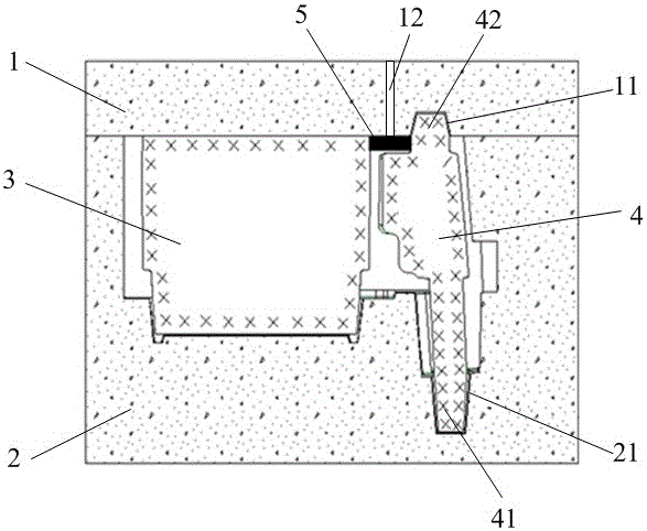
[0018] see figure 1 , the casting mold with the above-mentioned vertical sand core auxiliary positioning device includes an upper box 1, a lower box 2, a main sand core 3, a vertical sand core 4, a positioning part 5, the upper sand mold in the upper box 1 and the lower box 2 The lower sand mold is provided with a cavity for accommodating the main sand core 3 and the vertical sand core 4. The vertical sand core 4 includes a lower core head 41 and a Lu core head 42. The upper core head 11 matched with the core head 42, the lower core head 21 matched with the lower core head 41 is set at the position where the lower sand mold and the lower core head 41 are facing each other, and the vertical sand core 4 is biased toward the pre-tilted side along the center of gravity Set the positioning piece 5, the positioning pi...


PUM


Abstract

The invention discloses a casting mold provided with a vertical-sand-core assistant positioning device and a positioning method.The casting mold comprises an upper box, a lower box, a main sand core, a vertical sand core and a positioning piece.The vertical sand core comprises a lower core head and a furnace core head, an upper mold core head is arranged at the portion, directly facing the furnace core head, of an upper sand mold, a lower mold core head is arranged at the portion, directly facing the lower core head, of a lower sand mold, and the positioning piece is arranged along the side, with the gravity center tending to pre-incline, of the vertical sand core, and is arranged between the vertical sand core and the main sand core so that it can be avoided that the vertical sand core slants towards the tending direction of the gravity center; the positioning piece is made from a polystyrene material, and an air hole or an oblate riser is formed in the portion, directly facing the positioning piece, of the upper sand mold.According to the casting mold and the positioning method, the vertical sand core is fixed through a high-temperature automatic-disappearing polystyrene material, box assembling is carried out after it is guaranteed that the position of the sand core is correct, and it is avoided that sand is attached to the furnace core head; as the furnace core head and the upper box are mutually fixed after box assembling, the positioning piece does not have effects any more, and the quality of a casting is not influenced after pouring.

Description

technical field [0001] The invention relates to the technical field of internal sand core positioning during sand core casting, in particular to a casting mold and a positioning method provided with a vertical sand core auxiliary positioning device. Background technique [0002] In the casting process design process, due to the needs of the process and the relationship between the structure of the casting itself, a vertical sand core is designed to position the core head to achieve the purpose of controlling the size of the casting, and some of the vertical sand cores are often tall and thin. After the sand core is assembled into the lower cavity, the sand core is unstable, the lower core head of the vertical sand core is not perpendicular to the lower box surface, and the gap between the Lu core head of the vertical sand core and the upper core head of the upper box is not vertical when the box is closed. There is a problem of rubbing sand. [0003] In actual production, t...

Claims


Application Information

Patent Timeline
Patent Type & Authority Applications(China)
IPC IPC(8): B22C9/02B22C9/10B22C21/14
CPCB22C9/02B22C9/106B22C21/14
Inventor 张红坎刘利平
Owner KOCEL EQUIP
Learn More