
Oncoming vehicle real-time detection-based control device and method for tunnel lighting system

A technology for tunnel lighting and real-time detection, applied in lighting devices, energy-saving control technology, and lamp circuit layout, etc., can solve problems such as driver visual stimulation, difficulty for vehicles to quickly perceive tunnel scenes, and immediate shutdown of lighting devices to improve safety. performance and comfort, saving tunnel lighting energy consumption, and the effect of consistent lighting intensity

Active Publication Date: 2016-07-06
SOUTH CHINA UNIV OF TECH
View PDF7 Cites 9 Cited by
  • Summary
  • Abstract
  • Description
  • Claims
  • Application Information

AI Technical Summary

Problems solved by technology

However, there are problems: when the vehicle enters the tunnel lighting control section, the solutions proposed by the two patents are to immediately turn on the section lighting device, and when the vehicle leaves the corresponding section, the lighting device is immediately turned off
This kind of tunnel lighting control scheme makes the light intensity change drastically, and when different vehicles enter the tunnel, the light and darkness alternately change, which seriously stimulates the driver's vision, making the driver repeatedly experience "dazzling" when entering and exiting the tunnel state, it is difficult to guarantee the driver's visual reliability
In addition, the scheme may make the tunnel lighting device completely closed, and it is difficult for vehicles entering the tunnel to perceive the tunnel scene in a timely manner, which poses a great safety hazard

Method used


Image

  • Oncoming vehicle real-time detection-based control device and method for tunnel lighting system
  • Oncoming vehicle real-time detection-based control device and method for tunnel lighting system
  • Oncoming vehicle real-time detection-based control device and method for tunnel lighting system

Examples


Embodiment Construction

[0045] The present invention will be further described in detail below in conjunction with the embodiments and the accompanying drawings, but the embodiments of the present invention are not limited thereto.

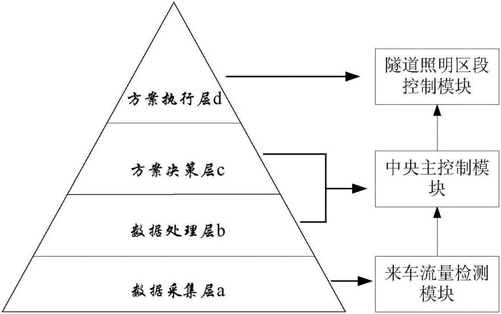
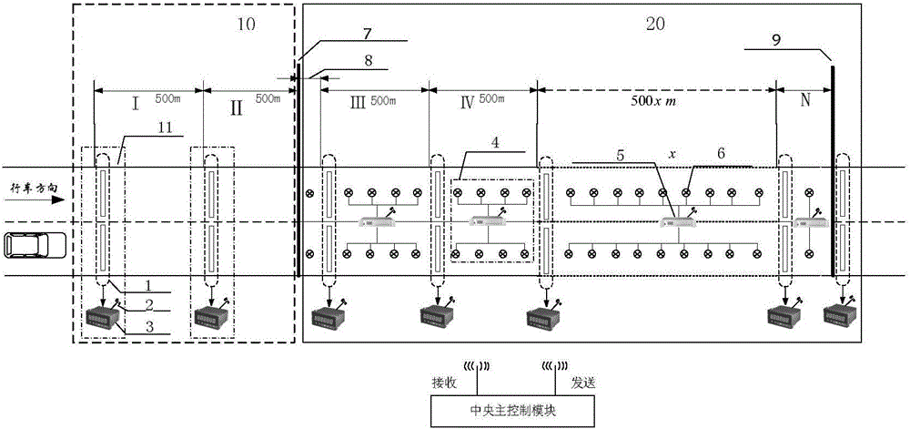
[0046] Such as figure 1 , 2 As shown, a control device for a tunnel lighting system based on real-time detection of incoming vehicles includes an incoming traffic flow detection module, a central main control module, and a tunnel lighting section control module. The incoming traffic flow detection module includes continuous equidistant A number of traffic flow detection sub-modules 11 distributed upstream of the tunnel entrance 7, inside the tunnel and at the tunnel exit 9 are used to obtain the traffic flow values ​​passing through each tunnel lighting section 4 and transmit them to the central main control module according to a predetermined time period; The central main control module is used to send corresponding lighting state control instructions to the tunnel lig...


PUM


Abstract

The invention discloses an oncoming vehicle real-time detection-based control device for a tunnel lighting system. The control device comprises a vehicle flow detection module, a central master control module and a tunnel lighting section control module, wherein the vehicle flow detection module comprises a plurality of oncoming vehicle flow detection sub-modules which are continuously distributed at the upstream part of a tunnel entrance, in a tunnel and at a tunnel exit at equal intervals along a road and are used for obtaining flow values of vehicles which pass through various tunnel lighting sections and periodically transmitting the flow values to the central master control module at preset time; the central master control module is used for comparing the flow values of the vehicles on a plurality of adjacent and continuous tunnel lighting sections and then transmitting a corresponding lighting state control instruction to the tunnel lighting section control module; and the tunnel lighting section control module comprises a plurality of tunnel lighting sub-controllers which are connected with lighting lamps of the lighting sections in the tunnel respectively. The invention further discloses an oncoming vehicle real-time detection-based control method for the tunnel lighting system. The oncoming vehicle real-time detection-based control device has the advantages of high actual adaptability and high operability, energy is saved and the traffic safety can be ensured.

Description

technical field [0001] The invention relates to the fields of expressway traffic safety, energy saving and emission reduction, and environmental protection, in particular to a control device and method for a tunnel lighting system based on real-time detection of incoming vehicles. Background technique [0002] The lighting system of the highway tunnel is an important part of the highway traffic engineering system. In terms of ensuring driving safety and improving driving comfort, the advantages and disadvantages of tunnel lighting artificial light environment play an important role. At present, the level of intelligent control and adaptive control of tunnel lighting systems in my country's highways is low, and there are many problems such as unreasonable brightness distribution and waste of electric energy. Specifically, when designing the lighting system of a tunnel in the past, the distribution and quantity of lamps in each section of the tunnel were determined based on h...

Claims


Application Information

Patent Timeline
Patent Type & Authority Applications(China)
IPC IPC(8): H05B37/02
CPCH05B47/115H05B47/19Y02B20/40
Inventor 温惠英刘敏靳辉游峰刘丹黄姣赵胜漆巍巍刘建荣
Owner SOUTH CHINA UNIV OF TECH
Learn More