
Mutually exclusive switching circuit

A switch circuit and switch technology, which is applied in the field of mutually exclusive switch circuits, can solve problems such as unsafe use, circuit short circuit, switch breakdown, etc., and achieve the effects of preventing components from burning, solving switch breakdown, and preventing circuit short circuit

Active Publication Date: 2016-07-06
山东泰开电力开关有限公司
View PDF4 Cites 1 Cited by
  • Summary
  • Abstract
  • Description
  • Claims
  • Application Information

AI Technical Summary

Problems solved by technology

[0002] The existing mutual exclusion switch is a pure digital circuit, the conduction angle cannot be adjusted, and the conduction angle overlaps, so that both switches may be conducted in a critical state, causing the circuit to short circuit and burning components; the power is small, and the electrical non-isolation , the use is unsafe, and the structure is complicated. In high-power occasions, it will cause the switch to break down and cannot be used.

Method used


Image

  • Mutually exclusive switching circuit
  • Mutually exclusive switching circuit
  • Mutually exclusive switching circuit

Examples


Embodiment Construction

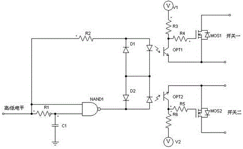
[0021] Such as figure 1 As shown, Embodiment 1 of the present invention includes a current limiting resistor R2, a delay module, a first NAND gate; the input terminal of the current limiting module, the input terminal of the delay module, and the first input terminal of the first NAND gate Both are connected to the switch control signal; the output end of the current limiting module and the output end of the first NAND gate are connected to the one-way conduction module; the two output ends of the one-way conduction module are respectively connected to a switch; the time delay The module includes a resistor R1 and a capacitor C1, the input terminal of the resistor R1 is connected to the switch control signal; the output terminal of the resistor R1 is connected to the second input terminal of the first NAND gate NAND1; one terminal of the capacitor C1 is connected to the Between the output end of the resistor R1 and the second input end of the first NAND gate NAND1, the other e...


PUM


Abstract

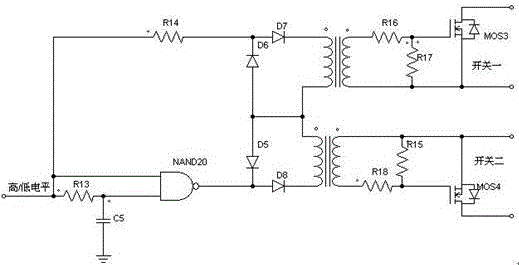
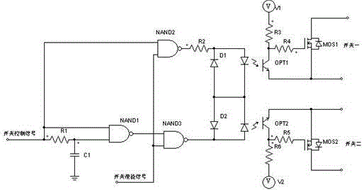
The invention discloses a mutually exclusive switching circuit. The mutually exclusive switching circuit comprises a current limiting module, a time delay module and a first NAND gate; an input end of the current limiting module, an input end of the time delay module and a first input end of the first NAND gate are connected to a switching control signal; an output end of the current limiting module and an output end of the first NAND gate are connected to a one-way conduction module; and two output ends of the one-way conduction module are each connected with a switching device. The mutually exclusive switching circuit disclosed by the invention is simple in structure, low in cost and easy to realize; the conduction angle of the mutually exclusive switching circuit can be adjusted by setting a parameter of the time delay module; the condition that two switches are simultaneously conducted in a critical state due to overlapping of the conduction angles can be effectively prevented; short circuit of the circuit is avoided, so that components are prevented from being burned; by means of electrical isolation, the mutually exclusive switching circuit can be used in a high-power occasion and is safe to use; and the problem that the switch is broken down easily in the mutually exclusive switching circuit in the prior art can be effectively solved.

Description

technical field [0001] The invention relates to a switch circuit, in particular to a mutually exclusive switch circuit. Background technique [0002] The existing mutual exclusion switch is a pure digital circuit, the conduction angle cannot be adjusted, and the conduction angle overlaps, so that both switches may be conducted in a critical state, causing the circuit to short circuit and burning components; the power is small, and the electrical non-isolation , the use is unsafe, and the structure is complicated. In high-power occasions, it will cause the switch to break down and cannot be used. Contents of the invention [0003] The technical problem to be solved by the present invention is to provide a mutually exclusive switch circuit for the deficiencies of the prior art. [0004] In order to solve the above technical problems, the technical solution adopted in the present invention is: a mutual exclusion switch circuit, including a current limiting module, a delay mo...

Claims


Application Information

Patent Timeline
Patent Type & Authority Applications(China)
IPC IPC(8): H03K17/78
CPCH03K17/78
Inventor 黄香春
Owner 山东泰开电力开关有限公司
Learn More