Dead beat control method of pulse width modulation (PWM) rectifier under unbalanced power grid voltage

A deadbeat control and grid voltage technology, applied in the direction of irreversible AC power input conversion to DC power output, etc., can solve problems such as reactive power fluctuations, grid voltage imbalance, and affecting system performance

Inactive Publication Date: 2016-07-06
CHINA UNIV OF MINING & TECH
View PDF5 Cites 6 Cited by
  • Summary
  • Abstract
  • Description
  • Claims
  • Application Information

AI Technical Summary

Problems solved by technology

[0004] At present, the research on the control method of the three-phase voltage PWM rectifier is mainly aimed at the grid voltage balance. In practice, when the grid has an asymmetrical fault or the three-phase load is unbalanced, the grid voltage will be unbalanced.
Under the unbalanced grid voltage, the grid voltage and current will generate positive and negative sequence components, resulting in active and reactive power fluctuations and unbalanced current distortion on the AC side, seriously affecting system performance
[0005] For the control of three-phase PWM rectifiers under unbalanced grid voltage, some scholars have proposed a deadbeat control method based on a stationary coordinate system. This method does not require rotating coordinate transformation, but its power compensation calculation still requires the extraction of positive and negative sequence components.

Method used


Image

  • Dead beat control method of pulse width modulation (PWM) rectifier under unbalanced power grid voltage
  • Dead beat control method of pulse width modulation (PWM) rectifier under unbalanced power grid voltage
  • Dead beat control method of pulse width modulation (PWM) rectifier under unbalanced power grid voltage

Examples


Embodiment Construction

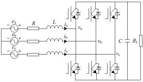
[0010] The present invention will be further described below in conjunction with the drawings. The main circuit topology of the three-phase voltage type PWM rectifier is as figure 1 Shown, e a , E b , E c Is the three-phase grid phase voltage, i a , I b , I c Input phase current for the three-phase PWM rectifier, v a , V b , V c Is the phase voltage of the AC side of the three-phase PWM rectifier, L and R are the inductance and equivalent resistance of the three-phase AC reactor, C is the DC filter capacitor, R L It is the equivalent resistance of the DC side load.

[0011] In the case of unbalanced grid voltage, for a three-phase non-neutral system, the grid voltage vector, grid current vector and rectifier AC side voltage vector can be expressed as

[0012] (1)

[0013] (2)

[0014] In the formula, the superscript p and n represent the positive and negative sequence components respectively; the subscript , Stand for rest coordinate system , Axis component; subscripts d and q r...


PUM


Abstract

The invention discloses a dead beat control method of a pulse width modulation (PWM) rectifier under unbalanced power grid voltage. In the technical scheme, the dead beat control method comprises the following steps subtracting a DC bus voltage given value from an actual value thereof; obtaining an active power given value under the balanced power grid voltage through a proportion integral (PI) controller; carrying out compensation power calculation on the active power given value under the power voltage after 90-degree delay and the balanced power voltage to obtain a power compensation value under the unbalanced power grid voltage, wherein the power compensation value is added to the power given value under the balanced power grid voltage to serve as the power given value under the unbalanced power grid voltage; and calculating to obtain an input voltage reference value under a two-phase static coordinate by a dead beat controller, wherein a switch signal for controlling a power device is generated after space vector pulse width modulation is carried out on the voltage signal. Under the unbalanced power grid voltage, the power fluctuation of the PWM rectifier can be compensated in no need of positive and negative sequence separation, thus, three different control targets of achieving symmetrical sine current of a network side, eliminating active power fluctuation and eliminating reactive power fluctuation are achieved, the system performance is improved, and the system structure is simplified.

Description

Technical field [0001] The invention relates to a control method of a voltage-type PWM rectifier under unbalanced grid voltage, belonging to the field of power electronic power conversion device control, in particular to a deadbeat control method of a PWM rectifier under unbalanced grid voltage. Background technique [0002] Voltage-type PWM rectifier has the advantages of controllable power factor, low input current harmonics, stable output DC voltage and bidirectional energy flow. It is used in AC electric drives, active power filtering, reactive power compensation, high-voltage DC transmission and new energy. Grid power generation and other fields have been widely used. [0003] Deadbeat control realizes the prediction of the given value at the beginning of the next cycle in each switching cycle, so as to control the system. It has the advantages of simple algorithm, precise control, and fast dynamic response. The direct power control method based on deadbeat does not need a ph...

Claims


Application Information

Patent Timeline
IPC IPC(8): H02M7/12
CPCH02M7/12
Inventor 严广蔡世冠李传号丁欣刘毅
Owner CHINA UNIV OF MINING & TECH
Why Eureka
Try Eureka