Positive and reverse rotation overload unloading valve

An unloading valve, forward and reverse technology, applied in the direction of fluid pressure actuation device, fluid pressure actuation system safety, servo motor components, etc., to prevent damage

Inactive Publication Date: 2016-07-06
宁波诚威液压科技有限公司
View PDF5 Cites 2 Cited by
  • Summary
  • Abstract
  • Description
  • Claims
  • Application Information

AI Technical Summary

Problems solved by technology

The above-mentioned system has high-pressure self-control overflow and low-pressure control unloading functions, but at the same time there is a defect: it cannot realize high-pressure self-control unloading of the positive oil circuit on the same valve body, and unloading of the low-pressure control positive oil circuit

Method used


Image

  • Positive and reverse rotation overload unloading valve
  • Positive and reverse rotation overload unloading valve
  • Positive and reverse rotation overload unloading valve

Examples


Embodiment Construction

[0017] The present invention will be further described below in conjunction with the drawings and specific embodiments.

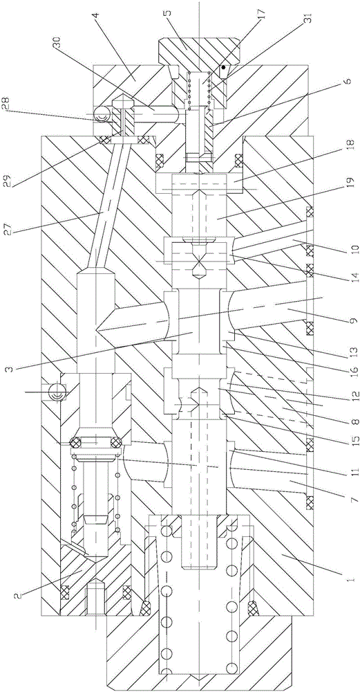
[0018] The working principle of the present invention: when the oil pump is rotating forward, the pressure oil from the oil outlet of the oil pump flows through the oil inlet 9 and the one-way valve 2 on the valve body 1, and then is output from the oil outlet 7 to the oil inlet cavity of the oil cylinder, thereby Make the oil cylinder do work; at the same time, as the pressure of the oil inlet 9 gradually increases, the pressure oil will also flow through the third channel 27, the orifice 29, and the fourth channel 30 to feed back to the first sealed oil chamber on the right end of the control spool 6. 17. Make the control spool 6 overcome the spring force of the spring pressure-regulating assembly, and gradually push the secondary pressure-bearing spool 19 and the main spool 3 to move to the left; until the control spool 6 is provided with a pressure regulati...


PUM


Abstract

The invention discloses a positive and reverse rotation overload unloading valve. The valve comprises a valve body (1), a one-way valve (2), a main valve core (3), an end cover (4), a plug (5), a control valve core (6) and a spring pressure regulating component, wherein an oil discharge duct (7), an oil return duct (8), an oil inlet duct (9) and a reverse oil duct (10) are formed in the valve body (1); the one-way valve (2) is communicated with the oil inlet duct (9) and the oil discharge duct (7); a runner structure used for unloading is arranged on the valve body (1); a first sealing oil cavity (17) is arranged between the control valve core (6) and the plug (5); a first oil duct mechanism is arranged between the oil inlet duct (9) and the first sealing oil cavity (17); a secondary pressure bearing valve core (19) is connected with the valve body (1) in a sliding manner. The valve can realize both positive oil duct high pressure self-control unloading and reverse low pressure control oil discharge duct oil return on one valve body.

Description

Technical field [0001] The invention relates to the technical field of hydraulic systems, in particular to a forward and reverse overload unloading valve. Background technique [0002] At present, the hydraulic oil circuit system of double-acting cylinders usually includes double-acting cylinders, oil pumps, motors, oil tanks, one-way valves, high-pressure relief valves, low-pressure relief valves, and hydraulic valves. The motors are used to drive the oil pump and the oil pumps are respectively It is connected to the oil tank, one-way valve, high pressure relief valve, low pressure relief valve and the rod oil cavity and rodless oil cavity of the cylinder. The overflow ports of the high pressure relief valve and the low pressure relief valve are connected to the oil tank. Both the direction valve and the hydraulic valve are connected to the rodless oil chamber of the cylinder, and the hydraulic valve is connected to the low pressure relief valve. The function of the hydraulic o...

Claims


Application Information

Patent Timeline
Patent Type & Authority Applications(China)
IPC IPC(8): F15B13/02F15B20/00
CPCF15B13/025F15B20/007
Inventor 韩峰林后玉王总建
Owner 宁波诚威液压科技有限公司
Why Eureka
Try Eureka