Spare wheel carrier for vehicle
A technology for spare tire racks and vehicles, which is applied in the layout of spare tires, vehicle components, transportation and packaging, etc., and can solve problems such as increasing the space distance between the door and the spare tire, difficulty in opening and closing the door, deformation and vibration of the linkage mechanism, etc. , to achieve the effect of compact structure, simple and convenient operation, and low production volume
- Summary
- Abstract
- Description
- Claims
- Application Information
AI Technical Summary
Problems solved by technology
Method used
Image
Examples
Embodiment 1
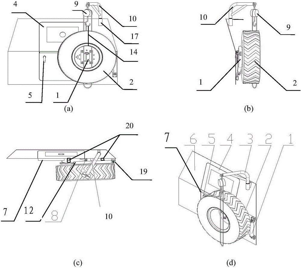
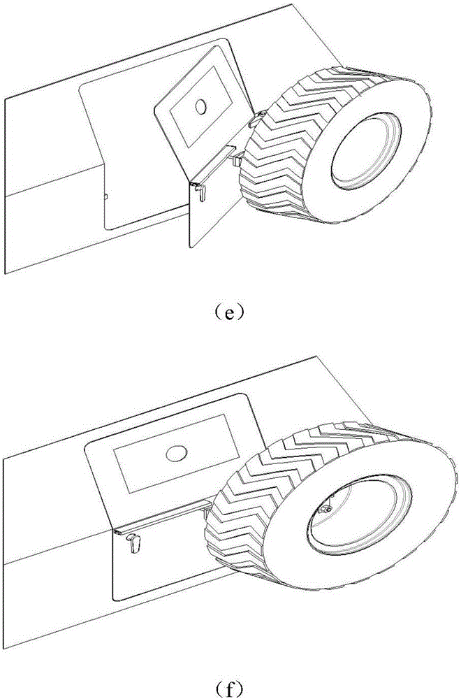
[0040] figure 1 shows the vehicle spare tire frame structure of the present invention, image 3 (a)~(d) show the structure of the vehicle spare tire rack without the spare tire installed.
[0041] A spare tire rack for a vehicle, comprising:
[0042] Spare tire fixing bracket 1: set on the outside of the door 4, the spare tire fixing bracket 1 and the spare tire 2 are assembled together;
[0043] Spare tire follow-up device 7: connected between the spare tire fixing bracket 1 and the car door 4, and realizes the spare tire fixing bracket 1 and the car door 4 to move with each other.
[0044] image 3 Shows the structure of the vehicle spare tire rack without the spare tire installed;
[0045] Spare wheel fixing bracket 1 includes:
[0046] Spare tire rack rotation spindle 11: parallel to the axis of rotation of the door 4, independent of the rotation of the door 4; the spare tire rack rotation spindle 11 is as Figure 6 As shown in (a) to (c), the rotating main shaft 11 ...
Embodiment 2
[0054] figure 1 Shown is the vehicle spare tire frame structure of the present invention;
[0055] A spare tire rack for a vehicle, comprising:
[0056] Spare tire fixing bracket 1: set on the outside of the door 4, the spare tire fixing bracket 1 and the spare tire 2 are assembled together;
[0057] Spare tire follow-up device 7: connected between the spare tire fixing bracket 1 and the car door 4, to realize the follow-up cooperation between the spare tire fixing bracket 1 and the car door 4.
[0058] image 3Shows the structure of the vehicle spare tire rack without the spare tire installed;
[0059] Spare wheel fixing bracket 1 includes:
[0060] Spare tire rack rotating main shaft 11: vertically assembled on the carriage door frame 6, parallel to the rotating shaft of the car door 4 in the axial direction, independent of the car door 4 rotating movement; the spare tire rack rotating main shaft 11 is as Figure 6 (a) ~ (c) shown.
[0061] The fixed support 12 and the...
Embodiment 3
[0071] figure 1 Shown is the vehicle spare tire frame structure of the present invention;
[0072] A spare tire rack for a vehicle, comprising:
[0073] Spare tire fixing bracket 1: set on the outside of the door 4, the spare tire fixing bracket 1 and the spare tire 2 are assembled together;
[0074] Spare tire follow-up device 7: connected between the spare tire fixing bracket 1 and the car door 4, to realize the follow-up cooperation between the spare tire fixing bracket 1 and the car door 4.
[0075] image 3 Shown is the spare tire rack structure without spare tire installed; spare tire fixing bracket 1 includes:
[0076] Spare tire rack rotating main shaft 11: vertically assembled on the carriage door frame 6, parallel to the rotating shaft of the car door 4 in the axial direction, independent of the car door 4 rotating movement; the spare tire rack rotating main shaft 11 is as Figure 6 (a) ~ (c) shown. The spare tire carrier rotating main shaft 11 is a rotating sha...
PUM
 Abstract
Description
Claims
Application Information
 - Generate Ideas
- Intellectual Property
- Life Sciences
- Materials
- Tech Scout
- Unparalleled Data Quality
- Higher Quality Content
- 60% Fewer Hallucinations
Browse by: Latest US Patents, China's latest patents, Technical Efficacy Thesaurus, Application Domain, Technology Topic, Popular Technical Reports.
© 2025 PatSnap. All rights reserved.Legal|Privacy policy|Modern Slavery Act Transparency Statement|Sitemap|About US| Contact US: help@patsnap.com


