A spare tire rack for a vehicle

A technology for spare tire racks and vehicles, which is applied in spare tire layout, vehicle components, transportation and packaging, and can solve problems such as increasing the space distance between the car door and the spare tire, difficulty in opening and closing the door, deformation and vibration of the connecting rod mechanism, etc. , to achieve the effect of compact structure, simple and convenient operation, and low manufacturing cost

Active Publication Date: 2017-12-05
NO 6409 FACTORY PLA
View PDF8 Cites 0 Cited by
  • Summary
  • Abstract
  • Description
  • Claims
  • Application Information

AI Technical Summary

Problems solved by technology

The existing problems are: (1) When the tire is large and heavy, it is difficult to open and close the door (2) The door is deformed due to the gravity of the spare tire and the vibration of the vehicle, and it is difficult to open and close the door (3) The diameter of the spare tire is larger than For the width of the car door, the space distance between the car door and the spare tire needs to be increased through the spare tire rack, so as to meet the space position requirement that the car door can be opened normally without interference
The existing problems are: (1) The parallel four-bar linkage mechanism requires high precision in the assembly position, and door opening and closing failures are prone to occur after the door is deformed. (2) Due to the large diameter of the tire, the parallel four-bar linkage mechanism will The space occupied between the spare wheel and the door is large and not compact
(3) Affected by the gravity of the spare tire and the turbulence of the vehicle, the connecting rod mechanism deforms and vibrates, making it difficult to open and close the door
[0007] 3. There is no suitable assembly plan and no equipment tires

Method used


Image

  • A spare tire rack for a vehicle
  • A spare tire rack for a vehicle
  • A spare tire rack for a vehicle

Examples


Embodiment 1

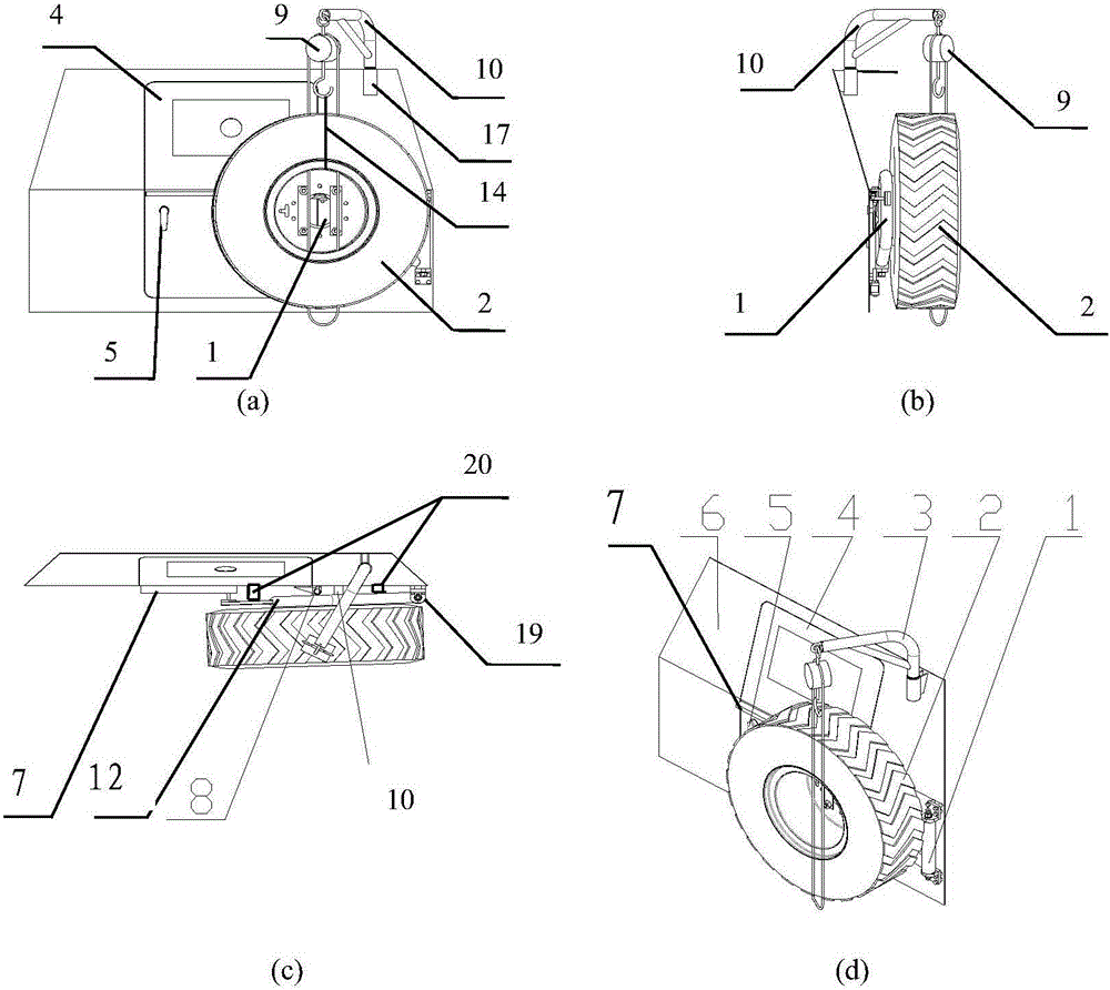
[0040] figure 1 shows the vehicle spare tire frame structure of the present invention, image 3 (a)~(d) show the structure of the vehicle spare tire rack without the spare tire installed.

[0041] A spare tire rack for a vehicle, comprising:

[0042] Spare tire fixing bracket 1: set on the outside of the door 4, the spare tire fixing bracket 1 and the spare tire 2 are assembled together;

[0043] Spare tire follow-up device 7: connected between the spare tire fixing bracket 1 and the car door 4, and realizes the spare tire fixing bracket 1 and the car door 4 to move with each other.

[0044] image 3 Shows the structure of the vehicle spare tire rack without the spare tire installed;

[0045] Spare wheel fixing bracket 1 includes:

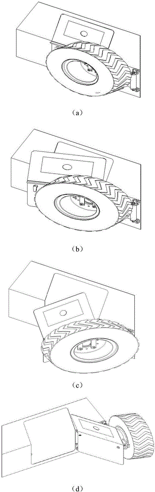
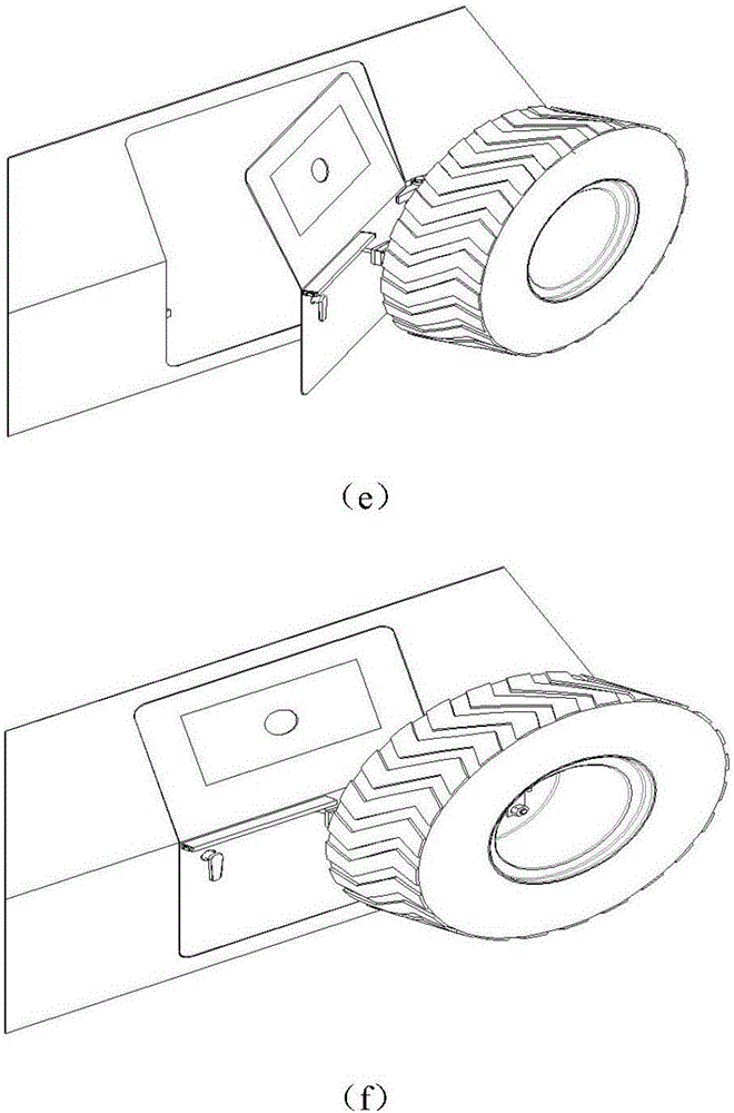
[0046] Spare tire rack rotation spindle 11: parallel to the axis of rotation of the door 4, independent of the rotation of the door 4; the spare tire rack rotation spindle 11 is as Image 6 As shown in (a) to (c), the rotating main shaft 11 o...

Embodiment 2

[0054] figure 1 Shown is the vehicle spare tire frame structure of the present invention;

[0055] A spare tire rack for a vehicle, comprising:

[0056] Spare tire fixing bracket 1: set on the outside of the door 4, the spare tire fixing bracket 1 and the spare tire 2 are assembled together;

[0057] Spare tire follow-up device 7: connected between the spare tire fixing bracket 1 and the car door 4, to realize the follow-up cooperation between the spare tire fixing bracket 1 and the car door 4.

[0058] image 3Shows the structure of the vehicle spare tire rack without the spare tire installed;

[0059] Spare wheel fixing bracket 1 includes:

[0060] Spare tire rack rotating main shaft 11: vertically assembled on the carriage door frame 6, parallel to the rotating shaft of the car door 4 in the axial direction, independent of the car door 4 rotating movement; the spare tire rack rotating main shaft 11 is as Image 6 (a) ~ (c) shown.

[0061] The fixed support 12 and the ...

Embodiment 3

[0071] figure 1 Shown is the vehicle spare tire frame structure of the present invention;

[0072] A spare tire rack for a vehicle, comprising:

[0073] Spare tire fixing bracket 1: set on the outside of the door 4, the spare tire fixing bracket 1 and the spare tire 2 are assembled together;

[0074] Spare tire follow-up device 7: connected between the spare tire fixing bracket 1 and the car door 4, to realize the follow-up cooperation between the spare tire fixing bracket 1 and the car door 4.

[0075] image 3 Shown is the spare tire rack structure without spare tire installed; spare tire fixing bracket 1 includes:

[0076] Spare tire rack rotating main shaft 11: vertically assembled on the carriage door frame 6, parallel to the rotating shaft of the car door 4 in the axial direction, independent of the car door 4 rotating movement; the spare tire rack rotating main shaft 11 is as Image 6 (a) ~ (c) shown. The spare tire carrier rotating main shaft 11 is a rotating shaf...


PUM


Abstract

The invention provides a spare wheel carrier for a vehicle. The spare wheel carrier comprises a spare wheel fixing support and a spare wheel follow-up device, wherein the spare wheel fixing support is arranged on the outer side of a vehicle door and assembled with a spare wheel; and the spare wheel follow-up device is connected between the spare wheel fixing support and the vehicle door, and the spare wheel fixing support and the vehicle door are matched in movement. The spare wheel carrier for the vehicle is provided with an independent rotary shaft, namely a spare wheel carrier rotary spindle, and the pare wheel carrier rotary spindle is matched with a driving sliding way in movement through a guide wheel, and therefore the spare wheel moves along with the vehicle door when the vehicle door is opened and closed. By the adoption of the spare wheel carrier, after the vehicle door is opened, the structure between the vehicle door and the spare wheel is compact, occupied space is small, and the problems that the vehicle door deforms or is opened in a labor-consuming manner due to the effect of external force of a related part are solved. The spare wheel carrier for the vehicle is provided with a quick wheel disassembling and assembling lifting tool, and the quick wheel disassembling and assembling lifting tool is installed on a shaft sleeve above the side of the vehicle door when the spare wheel is disassembled and assembled and is stored when the spare wheel is disassembled and assembled completely. Therefore, the attractiveness of a vehicle body is not affected, the spare wheel is quickly disassembled and assembled, operation is easy and convenient, and implementation is easy.

Description

technical field [0001] The invention relates to the technical field of wheeled vehicles, in particular to a vehicle spare tire rack. Background technique [0002] In the past, the used spare tires of wheeled vehicles are usually fixed under the chassis of the vehicle, or fixed on the rear of the vehicle, on the top of the vehicle, on both sides of the vehicle, inside the vehicle or other parts of the vehicle. [0003] Some special vehicles have higher technical index requirements for approach angle, departure angle, chassis height from the ground, body width, and compartment space, and the parts for conventional vehicles to install spare tires are restricted here; After the spare tire is installed nearby, it is necessary to ensure that the door can be opened and closed quickly from both the interior and exterior of the carriage, and the reliability is stable. [0004] When the above technical indicators require that the spare tire is only allowed to be installed on the rear...

Claims


Application Information

Patent Timeline
Patent Type & Authority Patents(China)
IPC IPC(8): B62D43/02
CPCB62D43/02
Inventor 梁光辉祝德元冯德杰周建波阎杰
Owner NO 6409 FACTORY PLA
Why Eureka
Try Eureka